automation
328 TopicsFrom Chat to Config: Building an AI-Native MCP Server for F5 Distributed Cloud
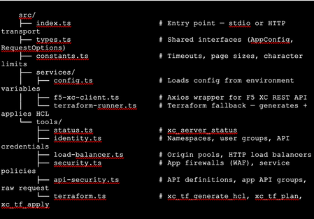
The Problem: F5 Distributed Cloud is Powerful but Verbose Anyone who has worked with F5 Distributed Cloud (XC) knows the platform is incredibly capable. HTTP load balancers, WAF policies, API security, origin pools, namespaces, service policies—the feature set is deep. But with depth comes complexity. A single POST to create an HTTP load balancer with WAF, HTTPS auto-cert, and an origin pool involves carefully crafting nested JSON across three or four separate API calls, each with its own spec structure. For experienced engineers, this is manageable. But what if you could just say: "Create an HTTPS load balancer for test-namespace, attach a WAF policy in blocking mode, origin server at 10.10.10.10 port 80 with an HTTP health check, auto-cert on port 443 with HTTP redirect" …and have all of that happen automatically, correctly, with dry-run safety by default? That's exactly what I built. This article walks through the F5 XC MCP Server—an open-source Model Context Protocol server that translates natural language commands from Claude Code or GitHub Copilot directly into F5 XC API calls. What is MCP? Model Context Protocol (MCP) is an open standard introduced by Anthropic that lets AI assistants (like Claude) call external tools and services through a structured interface. Think of it as a plugin system for AI — instead of the AI just generating text, it can actually do things: query APIs, read files, run commands, interact with platforms. An MCP server exposes a set of tools—typed functions with names, descriptions, and input schemas. When you ask Claude Code something like "list all my namespaces in F5 XC," it finds the right tool (xc_list_namespaces), calls it with the right parameters, and shows you the result. No copy-pasting API tokens into curl commands. No hunting through docs for the right endpoint path. MCP clients could be the popular AI coding tool, or any custom build MCP client, such as: Claude Code (via VS Code extension—the one I primarily used) GitHub Copilot (via VS Code extension) Any MCP-compatible client MCP servers can run locally (via stdio) or remotely (via HTTP/HTTPS). Architecture The server is built in TypeScript using the @modelcontextprotocol/sdk, with axios for F5 XC API calls and zod for input validation. The structure is intentionally simple: Key design decisions: Dry-run by default. F5_XC_DRY_RUN=true is the default. Every mutating call returns a preview of what would be sent rather than actually calling the API. This makes it safe to explore and prototype without fear. Set F5_XC_DRY_RUN=false when you're ready to go live. Dual auth. Supports both API token (Authorization: APIToken …) and mTLS certificate auth (https.Agent with PEM cert + key). The certificate extracted from the F5 XC .p12 credential file works directly. Dual transport. stdio for local use with Claude Code/Copilot; streamable HTTP/HTTPS for team-shared remote deployment. Terraform as fallback. When the REST API doesn't support an operation (more on this below), tools automatically generate ready-to-apply Terraform HCL using the volterraedge/volterra provider. The Four Use Cases The server covers four areas matching common F5 XC workflows: UC Tools Example operations UC-1 Identity Namespace CRUD, API credentials Create namespace, list users/groups, audit credentials UC-2 Load Balancer Origin pool CRUD, HTTP LB CRUD Create HTTPS LB with auto-cert, add origin pool UC-3 Security App Firewall (WAF) CRUD, Service Policy CRUD Create WAF in blocking mode, attach to LB UC-4 API Security API definition CRUD, App API group CRUD, raw request Import OpenAPI spec, create API group In total the server exposes 39 tools—enough to cover the majority of day-to-day F5 XC operations from a conversation. A Live Demo Walkthrough Here's a real session—every one of these was a natural language instruction to Claude Code, which called the appropriate MCP tool automatically. Step 1: Create a namespace "Create a new namespace called test-namespace" Step 2: Create an HTTP load balancer — then upgrade it "Create an HTTP load balancer named test-http-lb in test-namespace" The tool calls xc_create_http_lb with a minimal spec. State returns as VIRTUAL_HOST_READY in seconds. "Change protocol from HTTP to HTTPS port 443, use automatic certificate management from XC, add origin server 10.10.10.10 port 80 with default HTTP health check" This triggers three tool calls automatically: xc_raw_request → creates an HTTP healthcheck object xc_create_origin_pool → creates origin pool with 10.10.10.10:80, references the healthcheck Delete old LB + xc_create_http_lb → recreates as HTTPS with https_auto_cert, HTTP→HTTPS redirect, pool attached Note: F5 XC does not allow changing the LB type (HTTP → HTTPS) via PUT. The MCP server detected this and handled the delete-recreate flow automatically. The result: Step 3: Create and attach a WAF policy "Create a WAF policy named test-waf-policy" xc_create_app_firewall — blocking mode, default OWASP detection, default bot settings. Done in one call. test-waf-policy created ✓ Field Value Name test-waf-policy Namespace test-namespace Mode Blocking (blocks detected attacks) Detection Default OWASP ruleset Bot protection Default bot settings UID 8d350b72-5c8c-4e7c-b827-248b03067ed3 The WAF policy is ready. Would you like to attach it to test-http-lb? "Enable this WAF policy on test-http-lb" xc_update_http_lb — removes disable_waf, adds app_firewall reference. Verified with a GET to confirm disable_waf is gone and app_firewall.name is set. WAF policy enabled on test-httlp-lb ✓ Field Value WAF policy test-waf-policy (blocking mode) disable_waf removed LB state VIRTUAL_HOST_PENDING_A_RECORD Total time from zero to a WAF-protected HTTPS load balancer: under 2 minutes, all from natural language. The API Limitation Discovery — and the Terraform Fallback One of the most interesting findings during development: F5 XC's public REST API does not expose user/group write operations. Every path I tried returned either 404 or 501 Not Implemented: This is intentional by design—F5 XC routes user management through its Console UI. The Terraform volterraedge/volterra provider also didn’t help for users, group management. Rather than leaving the user with a dead end, I built a Terraform fallback: when a user group write fails, the tool’s response automatically includes: The AI can then call xc_tf_apply directly to execute it—or the user can copy the HCL and apply it themselves. The Terraform runner operates in isolated temp directories, cleans up after itself, and respects the global dryRun flag (plan instead of apply when dry-run is active). This pattern—REST first, Terraform as fallback—turned out to be a very useful architectural choice. It gracefully handles the gap between what the API exposes and what the platform can actually do. Deploying to Production: HTTPS with Automatic Certificates For a shared team tool, local stdio mode isn't enough. The server needs to be always-on, accessible over HTTPS, and with a real TLS certificate. The deployment stack on an Azure Ubuntu VM: Node.js 20 (via nvm) running the MCP server on port 3000 as a systemd service Caddy as a TLS-terminating reverse proxy—one config file, automatic Let's Encrypt The entire Caddy config: Caddy handles the ACME HTTP-01 challenge automatically. The Let's Encrypt certificate was issued in under 10 seconds after DNS propagated. Auto-renewal is built in—no cron jobs, no certbot timers. One gotcha worth noting: the default Caddy proxy timeout (30s) is shorter than some F5 XC API calls (namespace creation can take ~45s). The response_header_timeout 90s setting above is necessary. With this setup, the MCP endpoint is https://your-domain/mcp — usable from any MCP client without VPN or local server setup. Connecting Claude Code to the Remote Server Add this to your Claude Code MCP configuration (~/.claude.json or .claude/settings.json in your project): That's it. After a /mcp reload in Claude Code, all 39 tools are available. You can verify with: "Show me the F5 XC server status" Which calls xc_server_status and returns tenant, auth method, dry-run state, and Terraform auth status. Lessons Learned The F5 XC REST API is comprehensive for data plane operations, limited for identity management. Load balancers, WAF policies, origin pools, API definitions — all fully CRUD-able via REST. User and group management is not. Plan accordingly if your use case involves IAM automation. Dry-run mode is not optional — it's essential. Without it, a misunderstood instruction could delete a production load balancer. Making dry-run the default (and requiring explicit override per-call or globally) is the right design for any AI-driven ops tool. Tool descriptions matter more than you think. The quality of an MCP tool's description directly affects how accurately the AI uses it. Spending time writing precise, example-rich descriptions — including what fields are required, what values are valid, and what the return looks like — significantly improves the AI's ability to compose multi-step operations correctly. Graceful degradation beats hard failures. The Terraform fallback pattern is a good example. Rather than returning a cryptic API error and stopping, surfacing the equivalent HCL and offering to apply it keeps the workflow moving. Users get an answer even when the API says no. LB type changes require delete+recreate. The F5 XC API rejects PUT requests that change the load balancer type (e.g., HTTP → HTTPS). The MCP server handles this automatically by detecting the error and orchestrating the delete-recreate sequence — a good example of where the AI layer can absorb platform-specific quirks. What's Next This is v1.0 — functional, deployed, and covering the core use cases. Areas I'm exploring for future versions: API security scanning integration: trigger XC's web application scanning from the MCP server and return findings Multi-tenant support: switch tenants within a session without restarting the server Policy-as-code export: serialize existing LBs and WAF configs to Terraform HCL for IaC migration Audit/diff mode: compare current live config against a desired state and report drift Try It Yourself The server is open source on GitHub: https://github.com/gavinw2006/F5_XC_MCP_Server Prerequisites: Node.js 18+, an F5 XC tenant with an API token, and Claude Code or any MCP-compatible client. The first thing to try once connected: "Show me the F5 XC server status, then list all namespaces" Happy to hear feedback, questions, and PRs from the DevCentral community. If you build something on top of this—a new tool module, a different transport, integration with another F5 product—I’d love to know about it.505Views2likes2CommentsBulk-Create Secondary DNS Zones in F5 Distributed Cloud (via API)
If you’ve ever had to onboard dozens (or hundreds) of domains as secondary DNS zones in F5 Distributed Cloud (XC), you know the drill: click through the console, fill in the domain, add the primary server IP, save, repeat. It works - but it doesn’t scale. I ran into exactly this situation recently and figured a quick shell script would save me (and maybe you) a lot of clicking. What it does The script reads a simple text file - one domain per line, comma-separated with its primary DNS server IPs - and creates the corresponding secondary DNS zones via the F5 XC API. The input file looks like this: example.com, 10.0.0.1, 10.0.0.2 example.org, 192.168.1.1 internal.example.net, 172.16.0.1, 172.16.0.2, 172.16.0.3 Run the script, and it works through the list one by one: $ ./create_secondary_dns.sh Starting secondary DNS zone creation... Tenant : acmecorp --- [line 1] Creating secondary zone: example.com (primaries: 10.0.0.1 10.0.0.2) [line 1] OK - example.com created (HTTP 200) [line 2] Creating secondary zone: example.org (primaries: 192.168.1.1) [line 2] OK - example.org created (HTTP 200) --- Done. Success: 2, Failed: 0, Total lines: 2 That’s it. No Python, no Terraform, no extra frameworks - just bash, curl, and jq. TSIG support If your primary DNS servers require TSIG authentication for zone transfers, the script handles that too. Set the TSIG key name, algorithm, and secret in the configuration block, and the script will encrypt the secret locally using vesctl (the F5 XC CLI) before sending it to the API. If vesctl isn’t installed yet, the script downloads it automatically. If you don’t need TSIG, just leave the TSIG variables empty and the script skips that part entirely. Getting started 1. Clone the repo and navigate to the tool: git clone https://github.com/de1chk1nd/resources-and-tools.git cd resources-and-tools/tools/dns-secondary 2. Create your domain list: cp domains.txt.example domains.txt 3. Open the script and fill in your tenant name and API token: vi create_secondary_dns.sh 4. Run it: chmod +x create_secondary_dns.sh ./create_secondary_dns.sh The full README in the repository covers all configuration options, dependencies, and common error messages. What happens when something goes wrong? The script validates every line before hitting the API - domain names are checked for valid DNS characters, IP addresses are checked for valid IPv4 format. If a line is malformed, it’s skipped with a clear message and the script moves on to the next one. If a zone already exists in XC, the API returns a 409 and the script logs it as a failure but keeps going. At the end, you get a summary: how many succeeded, how many failed. A note on the repository This is a personal project, not an official F5 tool. It’s not supported by F5 and comes with no warranty. That said, it works well for my use cases and I hope it’s useful for yours too. If you run into issues or have suggestions, please open an issue on GitHub: GIT Repo The script lives here: DNS Tool463Views3likes1CommentLeveraging BGP and ECMP for F5 Distributed Cloud Customer Edge, Part Two
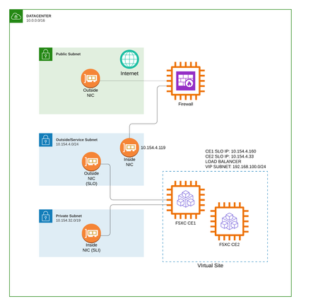
Introduction This is the second part of our series on leveraging BGP and ECMP for F5 Distributed Cloud Customer Edge deployments. In Part One, we explored the high-level concepts, architecture decisions, and design principles that make BGP and ECMP such a powerful combination for Customer Edge high availability and maintenance operations. This article provides step-by-step implementation guidance, including: High-level and low-level architecture diagrams Complete BGP peering and routing policy configuration in F5 Distributed Cloud Console Practical configuration examples for Fortinet FortiGate and Palo Alto Networks firewalls By the end of this article, you'll have everything you need to implement BGP-based high availability for your Customer Edge deployment. Architecture Overview Before diving into configuration, let’s establish a clear picture of the architecture we’re implementing. We’ll examine this from two perspectives: a high-level logical view and a detailed low-level view showing specific IP addressing and AS numbers. High-Level Architecture The high-level architecture illustrates the fundamental traffic flow and BGP relationships in our deployment: Key Components: Component Role Internet External connectivity to the network Next-Generation Firewall Acts as the BGP peer and performs ECMP distribution to Customer Edge nodes Customer Edge Virtual Site Two or more CE nodes advertising identical VIP prefixes via BGP The architecture follows a straightforward principle: the upstream firewall establishes BGP peering with each CE node. Each CE advertises its VIP addresses as /32 routes. The firewall, seeing multiple equal-cost paths to the same destination, distributes incoming traffic across all available CE nodes using ECMP. Low-Level Architecture with IP Addressing The low-level diagram provides the specific details needed for implementation, including IP addresses and AS numbers: Network Details: Component IP Address Role Firewall (Inside) 10.154.4.119/24 BGP Peer, ECMP Router CE1 (Outside) 10.154.4.160/24 Customer Edge Node 1 CE2 (Outside) 10.154.4.33/24 Customer Edge Node 2 Global VIP 192.168.100.10/32 Load Balancer VIP BGP Configuration: Parameter Firewall Customer Edge AS Number 65001 65002 Router ID 10.154.4.119 Auto-assigned based on interface IP Advertised Prefix None 192.168.100.0/24 le 32 This configuration uses eBGP (External BGP) between the firewall and CE nodes, with different AS numbers for each. The CE nodes share the same AS number (65002), which is the standard approach for multi-node CE deployments advertising the same VIP prefixes. Configuring BGP in F5 Distributed Cloud Console The F5 Distributed Cloud Console provides a centralized interface for configuring BGP peering and routing policies on your Customer Edge nodes. This section walks you through the complete configuration process. Step 1: Configure the BGP peering Go to: Multi-Cloud Network Connect --> Manage --> Networking --> External Connectivity --> BGP Peers & Policies Click on Add BGP Peer Then add the following information: Object name Site where to apply this BGP configuration ASN Router ID Here is an example of the required parameters. Then click on Peers --> Add Item And filled the relevant fields like below by adapting the parameters for your requirements. Step 2: Configure the BGP routing policies Go to: Multi-Cloud Network Connect --> Manage --> Networking --> External Connectivity --> BGP Peers & Policies --> BGP Routing Policies Click on Add BGP Routing Policy Add a name for your BGP routing policy object and click on Configure to add the rules. Click on Add Item to add a rule. Here we are going to allow the /32 prefixes from our VIP subnet (192.168.100.0/24). Save the BGP Routing Policy Repeat the action to create another BGP routing policy with the exact same parameters except the Action Type, which should be of type Deny. Now we have two BGP routing policies: One to allow the VIP prefixes (for normal operations) One to deny the VIP prefixes (for maintenance mode) We still need to a a third and final BGP routing policy, in order to deny any prefixes on the CE. For that, create a third BGP routing policy with this match. Step 3: Apply the BGP routing policies To apply the BGP routing policies in your BGP peer object, edit the Peer and: Enable the BGP routing policy Apply the BGP routing policy objects created before for Inbound and Outbound Fortinet FortiGate Configuration FortiGate firewalls are widely deployed as network security appliances and support robust BGP capabilities. This section provides the minimum configuration for establishing BGP peering with Customer Edge nodes and enabling ECMP load distribution. Step 1: Configure the Router ID and AS Number Configure the basic BGP settings: config router bgp set as 65001 set router-id 10.154.4.119 set ebgp-multipath enable Step 2: Configure BGP Neighbors Add each CE node as a BGP neighbor: config neighbor edit "10.154.4.160" set remote-as 65002 set route-map-in "ACCEPT-CE-VIPS" set route-map-out "DENY-ALL" set soft-reconfiguration enable next edit "10.154.4.33" set remote-as 65002 set route-map-in "ACCEPT-CE-VIPS" set route-map-out "DENY-ALL" set soft-reconfiguration enable next end end Step 3: Create Prefix List for VIP Range Define the prefix list that matches the CE VIP range: config router prefix-list edit "CE-VIP-PREFIXES" config rule edit 1 set prefix 192.168.100.0 255.255.255.0 set ge 32 set le 32 next end next end Important: The ge 32 and le 32 parameters ensure we only match /32 prefixes within the 192.168.100.0/24 range, which is exactly what CE nodes advertise for their VIPs. Step 4: Create Route Maps Configure route maps to implement the filtering policies: Inbound Route Map (Accept VIP prefixes): config router route-map edit "ACCEPT-CE-VIPS" config rule edit 1 set match-ip-address "CE-VIP-PREFIXES" next end next end Outbound Route Map (Deny all advertisements): config router route-map edit "DENY-ALL" config rule edit 1 set action deny next end next end Step 5: Verify BGP Configuration After applying the configuration, verify the BGP sessions and routes: Check BGP neighbor status: get router info bgp summary VRF 0 BGP router identifier 10.154.4.119, local AS number 65001 BGP table version is 4 1 BGP AS-PATH entries 0 BGP community entries Neighbor V AS MsgRcvd MsgSent TblVer InQ OutQ Up/Down State/PfxRcd 10.154.4.33 4 65002 2092 2365 0 0 0 00:05:33 1 10.154.4.160 4 65002 2074 2346 0 0 0 00:14:14 1 Total number of neighbors 2 Verify ECMP routes: get router info routing-table bgp Routing table for VRF=0 B 192.168.100.10/32 [20/255] via 10.154.4.160 (recursive is directly connected, port2), 00:00:11, [1/0] [20/255] via 10.154.4.33 (recursive is directly connected, port2), 00:00:11, [1/0] Palo Alto Networks Configuration Palo Alto Networks firewalls provide enterprise-grade security with comprehensive routing capabilities. This section covers the minimum BGP configuration for peering with Customer Edge nodes. Note: This part is assuming that Palo Alto firewall is configured in the new "Advanced Routing Engine" mode. And we will use the logical-router named "default". Step 1: Configure ECMP parameters set network logical-router default vrf default ecmp enable yes set network logical-router default vrf default ecmp max-path 4 set network logical-router default vrf default ecmp algorithm ip-hash Step 2: Configure objects IPs and firewall rules for BGP peering set address CE1 ip-netmask 10.154.4.160/32 set address CE2 ip-netmask 10.154.4.33/32 set address-group BGP_PEERS static [ CE1 CE2 ] set address LOCAL_BGP_IP ip-netmask 10.154.4.119/32 set rulebase security rules ALLOW_BGP from service set rulebase security rules ALLOW_BGP to service set rulebase security rules ALLOW_BGP source LOCAL_BGP_IP set rulebase security rules ALLOW_BGP destination BGP_PEERS set rulebase security rules ALLOW_BGP application bgp set rulebase security rules ALLOW_BGP service application-default set rulebase security rules ALLOW_BGP action allow Step 3: Palo Alto Configuration Summary (CLI Format) set network routing-profile filters prefix-list ALLOWED_PREFIXES type ipv4 ipv4-entry 1 prefix entry network 192.168.100.0/24 set network routing-profile filters prefix-list ALLOWED_PREFIXES type ipv4 ipv4-entry 1 prefix entry greater-than-or-equal 32 set network routing-profile filters prefix-list ALLOWED_PREFIXES type ipv4 ipv4-entry 1 prefix entry less-than-or-equal 32 set network routing-profile filters prefix-list ALLOWED_PREFIXES type ipv4 ipv4-entry 1 action permit set network routing-profile filters prefix-list ALLOWED_PREFIXES description "Allow only m32 inside 192.168.100.0m24" set network routing-profile filters prefix-list DENY_ALL type ipv4 ipv4-entry 1 prefix entry network 0.0.0.0/0 set network routing-profile filters prefix-list DENY_ALL type ipv4 ipv4-entry 1 prefix entry greater-than-or-equal 0 set network routing-profile filters prefix-list DENY_ALL type ipv4 ipv4-entry 1 prefix entry less-than-or-equal 32 set network routing-profile filters prefix-list DENY_ALL type ipv4 ipv4-entry 1 action deny set network routing-profile filters prefix-list DENY_ALL description "Deny all prefixes" set network routing-profile bgp filtering-profile FILTER_INBOUND ipv4 unicast inbound-network-filters prefix-list ALLOWED_PREFIXES set network routing-profile bgp filtering-profile FILTER_OUTBOUND ipv4 unicast inbound-network-filters prefix-list DENY_ALL set network logical-router default vrf default bgp router-id 10.154.4.119 set network logical-router default vrf default bgp local-as 65001 set network logical-router default vrf default bgp install-route yes set network logical-router default vrf default bgp enable yes set network logical-router default vrf default bgp peer-group BGP_PEERS type ebgp set network logical-router default vrf default bgp peer-group BGP_PEERS address-family ipv4 ipv4-unicast-default set network logical-router default vrf default bgp peer-group BGP_PEERS filtering-profile ipv4 FILTER_INBOUND set network logical-router default vrf default bgp peer-group BGP_PEERS filtering-profile ipv4 FILTER_OUTBOUND set network logical-router default vrf default bgp peer-group BGP_PEERS peer CE1 peer-as 65002 set network logical-router default vrf default bgp peer-group BGP_PEERS peer CE1 local-address interface ethernet1/2 set network logical-router default vrf default bgp peer-group BGP_PEERS peer CE1 local-address ip svc-intf-ip set network logical-router default vrf default bgp peer-group BGP_PEERS peer CE1 peer-address ip 10.154.4.160 set network logical-router default vrf default bgp peer-group BGP_PEERS peer CE2 peer-as 65002 set network logical-router default vrf default bgp peer-group BGP_PEERS peer CE2 local-address interface ethernet1/2 set network logical-router default vrf default bgp peer-group BGP_PEERS peer CE2 local-address ip svc-intf-ip set network logical-router default vrf default bgp peer-group BGP_PEERS peer CE2 peer-address ip 10.154.4.33 Step 4: Verify BGP Configuration After committing the configuration, verify the BGP sessions and routes: Check BGP neighbor status: run show advanced-routing bgp peer status logical-router default Logical Router: default ============== Peer Name: CE2 BGP State: Established, up for 00:01:55 Peer Name: CE1 BGP State: Established, up for 00:00:44 Verify ECMP routes: run show advanced-routing route logical-router default Logical Router: default ========================== flags: A:active, E:ecmp, R:recursive, Oi:ospf intra-area, Oo:ospf inter-area, O1:ospf ext 1, O2:ospf ext 2 destination protocol nexthop distance metric flag tag age interface 0.0.0.0/0 static 10.154.1.1 10 10 A 01:47:33 ethernet1/1 10.154.1.0/24 connected 0 0 A 01:47:37 ethernet1/1 10.154.1.99/32 local 0 0 A 01:47:37 ethernet1/1 10.154.4.0/24 connected 0 0 A 01:47:37 ethernet1/2 10.154.4.119/32 local 0 0 A 01:47:37 ethernet1/2 192.168.100.10/32 bgp 10.154.4.33 20 255 A E 00:01:03 ethernet1/2 192.168.100.10/32 bgp 10.154.4.160 20 255 A E 00:01:03 ethernet1/2 total route shown: 7 Implementing CE Isolation for Maintenance As discussed in Part One, one of the key advantages of BGP-based deployments is the ability to gracefully isolate CE nodes for maintenance. Here’s how to implement this in practice. Isolation via F5 Distributed Cloud Console To isolate a CE node from receiving traffic, in your BGP peer object, edit the Peer and: Change the Outbound BGP routing policy from the one that is allowing the VIP prefixes to the one that is denying the VIP prefixes The CE will stop advertising its VIP routes, and within seconds (based on BGP timers), the upstream firewall will remove this CE from its ECMP paths. Verification During Maintenance On your firewall, verify the route withdrawal (in this case we are using a Fortigate firewall): get router info bgp summary VRF 0 BGP router identifier 10.154.4.119, local AS number 65001 BGP table version is 4 1 BGP AS-PATH entries 0 BGP community entries Neighbor V AS MsgRcvd MsgSent TblVer InQ OutQ Up/Down State/PfxRcd 10.154.4.33 4 65002 2070 2345 0 0 0 00:04:05 0 10.154.4.160 4 65002 2057 2326 0 0 0 00:12:46 1 Total number of neighbors 2 We are not receiving any prefixes anymore for the 10.154.4.33 peer. get router info routing-table bgp Routing table for VRF=0 B 192.168.100.10/32 [20/255] via 10.154.4.160 (recursive is directly connected, port2), 00:06:34, [1/0] End we have now only one path. Restoring the CE in the data path After maintenance is complete: Return to the BGP Peer configuration in the F5XC Console Restore the original export policy (permit VIP prefixes) Save the configuration On the upstream firewall, confirm that CE prefixes are received again and that ECMP paths are restored Conclusion This article has provided the complete implementation details for deploying BGP and ECMP with F5 Distributed Cloud Customer Edge nodes. You now have: A clear understanding of the architecture at both high and low levels Step-by-step instructions for configuring BGP in F5 Distributed Cloud Console Ready-to-use configurations for both Fortinet FortiGate and Palo Alto Networks firewalls Practical guidance for implementing graceful CE isolation for maintenance By combining the concepts from the first article with the practical configurations in this article, you can build a robust, highly available application delivery infrastructure that maximizes resource utilization, provides automatic failover, and enables zero-downtime maintenance operations. The BGP-based approach transforms your Customer Edge deployment from a traditional Active/Standby model into a full active topology where every node contributes to handling traffic, and any node can be gracefully removed for maintenance without impacting your users.522Views3likes0CommentsMoving HTTP Load Balancers Between F5 Distributed Cloud Namespaces — Why It's Harder Than You Think
The Problem If you have been working with F5 Distributed Cloud (XC) for a while, you have probably run into this: your namespace structure no longer reflects how your teams or applications are organized. Maybe the initial layout was a quick decision during onboarding. Maybe teams have merged, projects have grown, or your naming convention has evolved. Either way, you now want to move a handful of HTTP load balancers from one namespace to another. Simple enough, right? Just change the namespace field and save... Except you can't. There is no "move" operation on F5 XC - not in the UI, not in the API. Changing the namespace of a load balancer means deleting it in the source and re-creating it in the target. And that is where things get complicated. Why a Simple Delete-and-Recreate Is Not Enough On the surface, the API is straightforward: "GET" the config, "DELETE" the object, "POST" it into the new namespace. But a production HTTP load balancer on XC is rarely a standalone object. It sits at the top of a dependency tree that can include origin pools, health checks, TLS certificates, service policies, app firewalls, rate limiters, and more. Every one of those dependencies needs to be handled correctly - or the migration breaks. Here are the main challenges we might run into. Referential Integrity F5 XC enforces strict referential integrity. You cannot delete an origin pool that is still referenced by a load balancer. You cannot create a load balancer that references an origin pool that does not exist yet. This means the order of operations matters: delete top-down (LBs first, then dependencies), create bottom-up (dependencies first, then LBs). It also means that if two load balancers share an origin pool, you cannot move them independently. Delete the first LB, try to delete the shared pool, and the API returns a 409 Conflict because the second LB still references it. Both LBs - and all of their shared dependencies - have to be moved together as a single atomic unit. New CNAMEs After Every Move When you delete and re-create an HTTP load balancer, F5 XC assigns a new "host_name" (the CNAME target that your DNS records point to). If the LB uses Let's Encrypt auto-certificates, the ACME challenge CNAME changes too. That means after every move, someone needs to update external DNS records - and until that happens, the application is unreachable or the TLS certificate renewal fails. For tenants using XC-managed DNS zones with "Allow Application Loadbalancer Managed Records" enabled, this is handled automatically. But many customers manage their own DNS, and they need the old and new CNAME values for every moved LB. Certificates with Non-Portable Private Keys This one is subtle. When a load balancer uses a manually imported TLS certificate, the private key is stored in one of several formats: blindfolded (encrypted with the Volterra blindfold key) or clear secret. In both of these cases, the XC API never returns the private key material in its GET response. You get the certificate and metadata, but not the key. That means you cannot extract-and-recreate the certificate in a new namespace via the API. Cross-namespace certificate references (outside of "shared" namespace) are also not supported. So if an LB in namespace A uses a manually imported certificate stored in namespace A, and you want to move that LB to namespace B, you need to first manually upload the same certificate into namespace B (or into the "shared" namespace) before the migration can proceed. API Metadata The XC API returns a "referring_objects" field on every config GET response. In theory, this tells you what other objects reference a given resource - exactly what you need to know before deleting something. In practice, this field can be empty even when active references exist. The only reliable way to detect all external references is to actively scan: fetch the config of every load balancer in the namespace and check their specs for references to the objects you are about to move. Cross-Namespace References Are Not Allowed On F5 XC, an HTTP load balancer can only reference objects in its own namespace, in "system" or "shared" namespace. If your origin pool lives in namespace A and you move the LB to namespace B, the origin pool must either come along to namespace B or already exist there. There is no way to have the LB in namespace B point to a pool in namespace A. This means you need to discover the complete transitive dependency tree of every LB, determine which dependencies need to move, detect which are shared between multiple LBs, and batch everything accordingly. The Tool: XC Namespace migration To deal with all of this, (A)I built **xc-ns-mover** — a Python CLI tool that automates the entire process. It has two components: Scanner - scans all namespaces on your tenant, lists every HTTP load balancer, and writes a CSV report. This gives you the inventory to decide what to move. Mover - takes a CSV of load balancers, discovers all dependencies, groups LBs that share dependencies into atomic batches, runs a series of pre-flight checks, and then executes the migration - or generates a dry-run report so you can review everything first, or do the job manually (JSON Code blocks available in the report) What the Mover Does Before Touching Anything The mover runs six pre-flight phases before making any changes: Discovery and batching - fetches every LB config, walks the dependency tree, and uses a union-find algorithm to cluster LBs with shared dependencies into batches. External reference scan - for every dependency being moved, checks whether any LB outside the move list references it. If so, that dependency cannot be moved without breaking the external LB, and the batch is blocked. Conflict detection - lists all existing objects in the target namespace. If a name already exists, the user can skip the object or rename it with a configurable prefix (e.g., "migrated-my-pool"). All internal JSON references are updated automatically. Certificate pre-flight - identifies certificates with non-portable private keys, then searches the target and "shared" namespaces for a matching certificate by domain/SAN comparison (including wildcard matching per RFC 6125). If a match is found, the LB's certificate reference is automatically rewritten. If not, the batch is blocked until the certificate is manually created. DNS zone pre-flight - queries the tenant's DNS zones to detect which ones have managed LB records enabled. LBs under managed zones are flagged as "auto-managed" in the report — no manual DNS update needed. After all checks pass, the actual migration follows a strict order per batch: backup everything, delete top-down, create bottom-up, verify new CNAMEs. If anything fails, automatic rollback kicks in — objects created in the target are deleted, objects deleted from the source are restored from backups. The Reports Every run produces an HTML report. The dry-run report shows planned configurations, the full dependency graph , certificate issues, DNS changes required, and any blocking issues — all before a single API call mutates anything. The post-migration report includes old and new CNAME values, a DNS changes table with exactly which records need updating, and full configuration backups of everything that was touched. Things to Keep in Mind A few caveats that are worth highlighting: Brief interruption is unavoidable - The migration deletes and re-creates load balancers. During that window (typically seconds to a few minutes per batch), traffic to affected domains will be impacted. Plan a change window. Only HTTP load balancers are supported - TCP load balancers and other object types are not handled by this tool. DNS updates are your responsibility - The report gives you all the values - old CNAME, new CNAME, ACME challenge CNAME - but you need to update your DNS provider. Always run the dry-run first - The tool enforces this by default: it stores a fingerprint after a dry-run and verifies it before executing. If the config changes, a new dry-run is required. The project is open source and available on GitHub. This is privately maintained and not "officially supported": https://github.com/de1chk1nd/resources-and-tools/blob/main/tools/xc-ns-mover/README.md If you find bugs or have feature requests, please open a GitHub issue.332Views4likes0CommentsAutomating Certificate Management on F5 BIG-IP
The Certificate Lifespan Revolution Welcome to part one of our two-part series on certificate automation for the BIG-IP platform. Certificate lifecycle management is undergoing a seismic shift that will fundamentally change how organizations handle SSL/TLS certificates. The era of comfortable 12-13 month certificate lifespans is rapidly ending. Major Certificate Authorities and browser vendors are pushing aggressively toward 90-day or even 47-day certificates, and some are proposing even shorter durations. This transformation represents more than a simple policy change. It's a complete paradigm shift that renders traditional certificate management approaches obsolete. The familiar rhythm of annual renewals, managed through spreadsheets and calendar reminders, becomes not just inefficient but operationally impossible when certificates expire every three months or 47 days. The Challenge: Why Manual Processes Are Doomed Organizations worldwide are recognizing the writing on the wall. Large PKI environments that once managed hundreds or thousands of certificates annually now face the prospect of managing them on a quarterly basis. The mathematical reality is stark: a 75% reduction in certificate lifespan translates to a 400% increase in the frequency of renewals. At F5, we hear you, we understand the anxiety this creates. We hear from customers daily who are grappling with this operational challenge. The F5 Solution: ACME Protocol Implementation While third-party vendors like Venafi and DigiCert offer comprehensive certificate automation platforms, this guide focuses on F5 solutions that leverage your existing BIG-IP infrastructure. Our approach is based on the ACME (Automatic Certificate Management Environment) protocol. This is the same technology that powers Let’s Encrypt and other modern certificate authorities. The solution uses a specialized ACME implementation called "dehydrated," adapted for BIG-IP by F5's own Kevin Stewart, with Python code inspired by Jason Rahm. You can read Kevin's DevCentral article here. Getting Started: Prerequisites and Setup Before diving into the implementation, ensure you have: Active BIG-IP with the LTM module and basic networking configured Registered domain with DNS management access for A record modifications (if setting up a new domain for testing purposes) Internet connectivity for downloading the ACME script and communicating with certificate authorities This solution is straightforward to configure and deploy. Follow along below. Step 1: Download and Explore Connect to your BIG-IP shell via SSH and download the script: curl -s https://raw.githubusercontent.com/f5devcentral/kojot-acme/main/install.sh | bash Navigate to the installation directory and explore the config file. This is where you can customize key size, contact information, OCSP stapling and more. cd /shared/acme The script adds a few new shiny toys to your BIG-IP. You will find two new data groups and a new iRule. The data group dg_acme_config houses the subject and CA or your certificate. We will need to modify this data group before we run the script; more on this in a moment. The dg_acme_challenge holds the challenge tokens and is ephemeral, cleaning up when the process completes. The iRule handles the HTTP-01 challenge. You need this iRule applied to the port 80 VIP when you run the script. At a high level, the iRule intercepts the challenge request from the ACME server and responds with an appropriate challenge response. In scenarios without a proxy, such as the BIG-IP, the web server handles this. Alternatively, you can use a DNS challenge by adding a TXT record at your registrar. The HTTP method is much simpler, so that’s what we will use here. Step 2: Configure Your Virtual IP Create an HTTP Virtual IP (VIP) to handle the ACME challenges. Production environments usually need both HTTP (port 80) and HTTPS (port 443) VIPs. Our demonstration uses a simple HTTP-only setup. Critical requirement: The ACME iRule must be applied to your port 80 VIP to enable HTTP-01 challenge processing. Step 3: Configure the Data Group - dg_acme_config We need to add our domain and CA information at a minimum. Add your domain to the string field and your CA information to the value field. See the documentation for more examples. Step 4: Configure DNS If you already have a domain configured pointing to your HTTP VIP, then skip this step. However, if you are setting up a new domain, please make sure that DNS is pointing to your VIP IP address or A record. For this demo, I purchased a low-cost domain and configured the A record to point to my AWS Elastic IP, which is attached to my private IP in my VPC. Step 5: Run the script Ok, you have DNS configured, VIP configured, and the data group modified with your domain and CA information. You are ready to roll. Go to the directory and run the script. cd /shared/acme ./f5acmehandler.sh -verbose The verbose flag provides real-time feedback on the ACME communication process, invaluable for troubleshooting and understanding the workflow. Success? If you are successful, you should see output similar to the screenshot below. If not, then the details of the script workflow should clue you into the problem. The GitHub repo also offers some troubleshooting advice. Also, let's see if we got a brand new shiny certificate. Yep. What's Next? While this created a cert and key, it didn't place them into an SSL profile. This is possible by modifying the config file. Scheduling checks could also be on your list. Kevin's article highlights this and provides an example. This will run the script every Monday at 4 am. ./f5acmehandler.sh --schedule "00 04 * * 1" There are other advanced capabilities that I did not configure or explain in this article. I encourage you to visit the DevCentral repo for more information. A key consideration for Federal agencies is the ability to support air-gapped or closed networks. However, requirements and compliance hurdles will need to be examined further. In the following article, we will cover the Certificate Order capability built into the BIG-IP. Until next time.11KViews1like3CommentsVIPTest: Rapid Application Testing for F5 Environments
VIPTest is a Python-based tool for efficiently testing multiple URLs in F5 environments, allowing quick assessment of application behavior before and after configuration changes. It supports concurrent processing, handles various URL formats, and provides detailed reports on HTTP responses, TLS versions, and connectivity status, making it useful for migrations and routine maintenance.1.2KViews5likes2CommentsiCall - All New Event-Based Automation System
The community has long requested the ability to affect change to the BIG-IP configuration by some external factor, be it iRules trigger, process or system failure event, or even monitor results. Well, rest easy folks, among the many features arriving with BIG-IP version 11.4 is iCall, a completely new event-based granular internal automation system. iCall gives you comprehensive control over BIG-IP configuration, leveraging the TMSH control plane and seamlessly integrating the data plane as well. Components The iCall system has three components: events, handlers, and scripts. At a high level, an event is "the message," some named object that has context (key value pairs), scope (pool, virtual, etc), origin (daemon, iRules), and a timestamp. Events occur when specific, configurable, pre-defined conditions are met. A handler initiates a script and is the decision mechanism for event data. There are three types of handlers: Triggered - reacts to a specific event Periodic - reacts to a timer Perpetual - runs under the control of a daemon Finally, there are scripts. Scripts perform the action as a result of event and handler. The scripts are TMSH Tcl scripts organized under the /sys icall section of the system. Flow Basic flows for iCall configurations start with an event followed by a handler kicking off a script. A more complex example might start with a periodic handler that kicks off a script that generates an event that another handler picks up and generates another script. These flows are shown in the image below. A Brief Example We'll release a few tech tips on the development aspect of iCall in the coming weeks, but in the interim here's a prime use case. Often an event will happen that an operator will want to grab a tcpdump on the interesting traffic occurring during that event, but the reaction time isn't quick enough. Enter iCall! First, configure an alert in /config/user_alert.conf for a pool member down: alert local-http-10-2-80-1-80-DOWN "Pool /Common/my_pool member /Common/10.2.80.1:80 monitor status down" { exec command="tmsh generate sys icall event tcpdump context { { name ip value 10.2.80.1 } { name port value 80 } { name vlan value internal } { name count value 20 } }" } You'll need one of these stanzas for each pool member you want to monitor in this way. Next, Create the iCall script: modify script tcpdump { app-service none definition { set date [clock format [clock seconds] -format "%Y%m%d%H%M%S"] foreach var { ip port count vlan } { set $var $EVENT::context($var) } exec tcpdump -ni $vlan -s0 -w /var/tmp/${ip}_${port}-${date}.pcap -c $count host $ip and port $port } description none events none } Finally, create the iCall handler to trigger the script: sys icall handler triggered tcpdump { script tcpdump subscriptions { tcpdump { event-name tcpdump } } } Ready. Set. Go! That's one example of a triggered handler. We have many more examples of perpetual and periodic handlers in the codeshare with several use cases for your immediate use and testing. Get ready to jump aboard the iCall automation/orchestration train!3.3KViews0likes4CommentsUsing Aliases to launch F5 AMI Images in AWS Marketplace
F5 lists 82 product offerings in the AWS Marketplace as Amazon Machine Images (AMI). Each version of each product in each AWS Region has a different AMI. That’s around 22,000 images! Each AMI is identified by an AMI ID. You use the AMI ID to indicate which AMI you want to use when launching an F5 product. You can find AMI IDs using the AWS Web Console, but the AWS CLI is the best tool for the job. Searching for AMIs using the AWS CLI Here’s how you find the AMI IDs for version 17.5.1.2 of BIG-IP Virtual Edition in the us-east-1 AWS region: aws ec2 describe-images --owners aws-marketplace --filters 'Name=name,Values=F5 BIGIP-17.5.1.2*' --query "sort_by(Images,&Name)[:]. {Description: Description, Id:ImageId }" --region us-east-1 --output table ---------------------------------------------------------------------------------------------------- | DescribeImages | +------------------------------------------------------------------------+-------------------------+ | Description | Id | +------------------------------------------------------------------------+-------------------------+ | F5 BIGIP-17.5.1.2-0.0.5 BYOL-All Modules 1Boot Loc-250916013758 | ami-0948eabdf29ef2a8f | | F5 BIGIP-17.5.1.2-0.0.5 BYOL-All Modules 2Boot Loc-250916015535 | ami-0cb3aaa67967ad029 | | F5 BIGIP-17.5.1.2-0.0.5 BYOL-LTM 1Boot Loc-250916013616 | ami-05d70b82c9031ff39 | | F5 BIGIP-17.5.1.2-0.0.5 BYOL-LTM 2Boot Loc-250916014744 | ami-0b6021cc939308f3e | | F5 BIGIP-17.5.1.2-0.0.5 BYOL-encrypted-threat-protection-250916015535 | ami-01f4fde300d3763be | | F5 BIGIP-17.5.1.2-0.0.5 PAYG-AWF Plus 16vCPU-250916015534 | ami-015474056159387ac | | F5 BIGIP-17.5.1.2-0.0.5 PAYG-Adv WAF Plus 200Mbps-250916015522 | ami-06ce5b03dce2a059d | | F5 BIGIP-17.5.1.2-0.0.5 PAYG-Adv WAF Plus 25Mbps-250916015520 | ami-0826808708df97480 | | F5 BIGIP-17.5.1.2-0.0.5 PAYG-Adv WAF Plus 3Gbps-250916015523 | ami-08c63c8f7ca71cf37 | | F5 BIGIP-17.5.1.2-0.0.5 PAYG-Best Plus 10Gbps-250916015532 | ami-0e806ef17838760e4 | | F5 BIGIP-17.5.1.2-0.0.5 PAYG-Best Plus 1Gbps-250916015530 | ami-05e31c2a0ac9ec050 | | F5 BIGIP-17.5.1.2-0.0.5 PAYG-Best Plus 200Mbps-250916015528 | ami-02dc0995af98d0710 | | F5 BIGIP-17.5.1.2-0.0.5 PAYG-Best Plus 25Mbps-250916015527 | ami-08b8f2daefde800e9 | | F5 BIGIP-17.5.1.2-0.0.5 PAYG-Best Plus 5Gbps-250916015531 | ami-0d16154bb1102f3e9 | | F5 BIGIP-17.5.1.2-0.0.5 PAYG-Better 10Gbps-250916015512 | ami-05c9527fff191feba | | F5 BIGIP-17.5.1.2-0.0.5 PAYG-Better 1Gbps-250916015510 | ami-05ce2932601070d5c | | F5 BIGIP-17.5.1.2-0.0.5 PAYG-Better 200Mbps-250916015508 | ami-0f6044db3900ba46f | | F5 BIGIP-17.5.1.2-0.0.5 PAYG-Better 25Mbps-250916014542 | ami-0de57aba160170358 | | F5 BIGIP-17.5.1.2-0.0.5 PAYG-Better 5Gbps-250916015511 | ami-04271103ab2d1369d | | F5 BIGIP-17.5.1.2-0.0.5 PAYG-Good 10Gbps-250916014739 | ami-0d06d2a097d7bb47a | | F5 BIGIP-17.5.1.2-0.0.5 PAYG-Good 1Gbps-250916014737 | ami-01707e969ebcc6138 | | F5 BIGIP-17.5.1.2-0.0.5 PAYG-Good 200Mbps-250916014735 | ami-06f9a44562d94f992 | | F5 BIGIP-17.5.1.2-0.0.5 PAYG-Good 25Mbps-250916013626 | ami-0aa2bca574c66af13 | | F5 BIGIP-17.5.1.2-0.0.5 PAYG-Good 5Gbps-250916014738 | ami-01951e02c52deef85 | | F5 BIGIP-17.5.1.2-0.0.5 PAYG-PVE Adv WAF Plus 200Mbps-0916015525 | ami-03df50dfc04f19df5 | | F5 BIGIP-17.5.1.2-0.0.5 PAYG-PVE Adv WAF Plus 25Mbps-50916015524 | ami-0777c069eaae20ea1 | +------------------------------------------------------------------------+-------------------------+ This command shows all 17.5.1* releases of the "PayGo Good 1Gbps" flavor of BIG-IP in the us-west-1 region sorted by newest release first: aws ec2 describe-images --owners aws-marketplace --filters 'Name=name,Values=F5 BIGIP-17.5.1*PAYG-Good 1Gbps*' --query "reverse(sort_by(Images,&CreationDate))[:]. {Description: Name, Id:ImageId , date:CreationDate}" --region us-west-1 --output table ---------------------------------------------------------------------------------------------------------------------------------------------------- | DescribeImages | +--------------------------------------------------------------------------------------------+------------------------+----------------------------+ | Description | Id | date | +--------------------------------------------------------------------------------------------+------------------------+----------------------------+ | F5 BIGIP-17.5.1.2-0.0.5 PAYG-Good 1Gbps-250916014737-7fb2f9db-2a12-4915-9abb-045b6388cccd | ami-0de8ca1229be5f7fe | 2025-09-16T23:12:28.000Z | | F5 BIGIP-17.5.1-0.80.7 PAYG-Good 1Gbps-250811055424-7fb2f9db-2a12-4915-9abb-045b6388cccd | ami-09afcec6f36494382 | 2025-08-15T19:03:23.000Z | | F5 BIGIP-17.5.1-0.0.7 PAYG-Good 1Gbps-250618090310-7fb2f9db-2a12-4915-9abb-045b6388cccd | ami-03e389e112872fd53 | 2025-07-01T06:00:44.000Z | +--------------------------------------------------------------------------------------------+------------------------+----------------------------+ Notice that the same BIG-IP VE release has a different AMI ID in each AWS region. Attempting to launch a product in one region using an AMI ID from a different region will fail. This causes a problem when a shell script or automation tool is used to launch new EC2 instances and the AMI IDs have been hardcoded for one region and you attempt to use it in another. Wouldn’t it be nice to have a single AMI identifier that works in all AWS regions? Introducing AMI Aliases The Ami Alias is a similar ID to the AMI ID, but it’s easier to use in automation. An AMI alias has the form /aws/service/marketplace/prod-<identifier>/<version> , for example, "PayGo Good 1Gbps" /aws/service/marketplace/prod-s6e6miuci4yts/17.5.1.2-0.0.5 You can use this Ami Alias ID in any Region, and AWS automatically maps it to the correct Regional AMI ID. BIG-IP AMI Alias Identifiers F5 Advanced WAF with LTM, IPI, and Threat Campaigns (PAYG, 16vCPU) prod-qqgc2ltsirpio F5 Advanced WAF with LTM, IPI, and Threat Campaigns (PAYG, 200Mbps) prod-yajbds56coa24 F5 Advanced WAF with LTM, IPI, and Threat Campaigns (PAYG, 25Mbps) prod-qiufc36l6sepa F5 Advanced WAF with LTM, IPI, and Threat Campaigns (PAYG, 3Gbps) prod-fp5qrfirjnnty F5 BIG-IP BEST with IPI and Threat Campaigns (PAYG, 10Gbps) prod-w2p3rtkjrjmw6 F5 BIG-IP BEST with IPI and Threat Campaigns (PAYG, 1Gbps) prod-g3tye45sqm5d4 F5 BIG-IP BEST with IPI and Threat Campaigns (PAYG, 200Mbps) prod-dnpovgowtyz3o F5 BIG-IP BEST with IPI and Threat Campaigns (PAYG, 25Mbps) prod-wjoyowh6kba46 F5 BIG-IP BEST with IPI and Threat Campaigns (PAYG, 5Gbps) prod-hlx7g47cksafk F5 BIG-IP VE - ALL (BYOL, 1 Boot Location) prod-zvs3u7ov36lig F5 BIG-IP VE - ALL (BYOL, 2 Boot Locations) prod-ubfqxbuqpsiei F5 BIG-IP VE - LTM/DNS (BYOL, 1 Boot Location) prod-uqhc6th7ni37m F5 BIG-IP VE - LTM/DNS (BYOL, 2 Boot Locations) prod-o7jz5ohvldaxg F5 BIG-IP Virtual Edition - BETTER (PAYG, 10Gbps) prod-emsxkvkzwvs3o F5 BIG-IP Virtual Edition - BETTER (PAYG, 1Gbps) prod-4idzu4qtdmzjg F5 BIG-IP Virtual Edition - BETTER (PAYG, 200Mbps) prod-firaggo6h7bt6 F5 BIG-IP Virtual Edition - BETTER (PAYG, 25Mbps) prod-wijbh7ib34hyy F5 BIG-IP Virtual Edition - BETTER (PAYG, 5Gbps) prod-rfglxslpwq64g F5 BIG-IP Virtual Edition - GOOD (PAYG, 10Gbps) prod-54qdbqglgkiue F5 BIG-IP Virtual Edition - GOOD (PAYG, 1Gbps) prod-s6e6miuci4yts F5 BIG-IP Virtual Edition - GOOD (PAYG, 200Mbps) prod-ynybgkyvilzrs F5 BIG-IP Virtual Edition - GOOD (PAYG, 25Mbps) prod-6zmxdpj4u4l5g F5 BIG-IP Virtual Edition - GOOD (PAYG, 5Gbps) prod-3ze6zaohqssua F5 BIG-IQ Virtual Edition - (BYOL) prod-igv63dkxhub54 F5 Encrypted Threat Protection prod-bbtl6iceizxoi F5 Per-App-VE Advanced WAF with LTM, IPI, TC (PAYG, 200Mbps) prod-gkzfxpnvn53v2 F5 Per-App-VE Advanced WAF with LTM, IPI, TC (PAYG, 25Mbps) prod-qu34r4gipys4s NGINX Plus Alias Identifiers NGINX Plus Basic - Amazon Linux 2 (LTS) AMI prod-jhxdrfyy2jtva NGINX Plus Developer - Amazon Linux 2 (LTS) prod-kbeepohgkgkxi NGINX Plus Developer - Amazon Linux 2 (LTS) ARM Graviton prod-vulv7pmlqjweq NGINX Plus Developer - Amazon Linux 2023 prod-2zvigd3ltowyy NGINX Plus Developer - Amazon Linux 2023 ARM Graviton prod-icspnobisidru NGINX Plus Developer - RHEL 8 prod-tquzaepylai4i NGINX Plus Developer - RHEL 9 prod-hwl4zfgzccjye NGINX Plus Developer - Ubuntu 22.04 prod-23ixzkz3wt5oq NGINX Plus Developer - Ubuntu 24.04 prod-tqr7jcokfd7cw NGINX Plus FIPS Premium - RHEL 9 prod-v6fhyzzkby6c2 NGINX Plus Premium - Amazon Linux 2 (LTS) AMI prod-4dput2e45kkfq NGINX Plus Premium - Amazon Linux 2 (LTS) ARM Graviton prod-56qba3nacijjk NGINX Plus Premium - Amazon Linux 2023 prod-w6xf4fmhpc6ju NGINX Plus Premium - Amazon Linux 2023 ARM Graviton prod-e2iwqrpted4kk NGINX Plus Premium - RHEL 8 AMI prod-m2v4zstxasp6s NGINX Plus Premium - RHEL 9 prod-rytmqzlxdneig NGINX Plus Premium - Ubuntu 22.04 prod-dtm5ujpv7kkro NGINX Plus Premium - Ubuntu 24.04 prod-opg2qh33mi4pk NGINX Plus Standard - Amazon Linux 2 (LTS) AMI prod-mdgdnfftmj7se NGINX Plus Standard - Amazon Linux 2 (LTS) ARM Graviton prod-2kagbnj7ij6zi NGINX Plus Standard - Amazon Linux 2023 prod-i25cyug3btfvk NGINX Plus Standard - Amazon Linux 2023 ARM Graviton prod-6s5rvlqlgrt74 NGINX Plus Standard - RHEL 8 prod-ebhpntvlfwluc NGINX Plus Standard - RHEL 9 prod-3e7rk2ombbpfa NGINX Plus Standard - Ubuntu 22.04 prod-7rhflwjy5357e NGINX Plus Standard - Ubuntu 24.04 prod-b4rly35ct3dlc NGINX Plus with NGINX App Protect Developer - Amazon Linux 2 prod-pjmfzy5htmaks NGINX Plus with NGINX App Protect Developer - Debian 11 prod-ixsytlu2eluqa NGINX Plus with NGINX App Protect Developer - RHEL 8 prod-6v57ggy3dqb6c NGINX Plus with NGINX App Protect Developer - Ubuntu 20.04 prod-4a4g7h7mpepas NGINX Plus with NGINX App Protect DoS Developer - Amazon Linux 2023 prod-fmqayhbsryoz2 NGINX Plus with NGINX App Protect DoS Developer - Debian 11 prod-4e5fwakhrn36y NGINX Plus with NGINX App Protect DoS Developer - RHEL 8 prod-ubid75ixhf34a NGINX Plus with NGINX App Protect DoS Developer - RHEL 9 prod-gg7mi5njfuqcw NGINX Plus with NGINX App Protect DoS Developer - Ubuntu 20.04 prod-qiwzff7orqrmy NGINX Plus with NGINX App Protect DoS Developer - Ubuntu 22.04 prod-h564ffpizhvic NGINX Plus with NGINX App Protect DoS Developer - Ubuntu 24.04 prod-wckvpxkzj7fvk NGINX Plus with NGINX App Protect DoS Premium - Amazon Linux 2023 prod-lza5c4nhqafpk NGINX Plus with NGINX App Protect DoS Premium - Debian 11 prod-ych3dq3r44gl2 NGINX Plus with NGINX App Protect DoS Premium - RHEL 8 prod-266ker45aot7g NGINX Plus with NGINX App Protect DoS Premium - RHEL 9 prod-6qrqjtainjlaa NGINX Plus with NGINX App Protect DoS Premium - Ubuntu 20.04 prod-hagmbnluc5zmw NGINX Plus with NGINX App Protect DoS Premium - Ubuntu 22.04 prod-y5iwq6gk4x4yq NGINX Plus with NGINX App Protect DoS Premium - Ubuntu 24.04 prod-k3cb7avaushvq NGINX Plus with NGINX App Protect Premium - Amazon Linux 2 prod-tlghtvo66zs5u NGINX Plus with NGINX App Protect Premium - Debian 11 prod-6kfdotc3mw67o NGINX Plus with NGINX App Protect Premium - RHEL 8 prod-okwnxdlnkmqhu NGINX Plus with NGINX App Protect Premium - Ubuntu 20.04 prod-5wn6ltuzpws4m NGINX Plus with NGINX App Protect WAF + DoS Premium - Amazon Linux 2023 prod-mualblirvfcqi NGINX Plus with NGINX App Protect WAF + DoS Premium - Debian 11 prod-k2rimvjqipvm2 NGINX Plus with NGINX App Protect WAF + DoS Premium - RHEL 8 prod-6nlubep3hg4go NGINX Plus with NGINX App Protect WAF + DoS Premium - Ubuntu 18.04 prod-f2diywsozd22m NGINX Plus with NGINX App Protect WAF + DoS Premium - Ubuntu 20.04 prod-ajcsh5wsfuen2 NGINX Plus with NGINX App Protect WAF + DoS Premium - Ubuntu 22.04 prod-6adjgf6yl7hek NGINX Plus with NGINX App Protect WAF + DoS Premium - Ubuntu 24.04 prod-autki7guiiqio Using AMI Aliases for BIG-IP The following example shows using an AMI alias to launch a new "F5 BIG-IP Virtual Edition - GOOD (PAYG, 1Gbps)" instance version 17.5.1.2-0.0.5 by using the AWS CLI. aws ec2 run-instances --image-id resolve:ssm:/aws/service/marketplace/prod-s6e6miuci4yts/17.5.1.2-0.0.5 --instance-type m5.xlarge --key-name MyKeyPair The next example shows a CloudFormation template that accepts the AMI alias as an input parameter to create an instance. AWSTemplateFormatVersion: 2010-09-09 Parameters: AmiAlias: Description: AMI alias Type: 'String' Resources: MyEC2Instance: Type: AWS::EC2::Instance Properties: ImageId: !Sub "resolve:ssm:${AmiAlias}" InstanceType: "g4dn.xlarge" Tags: -Key: "Created from" Value: !Ref AmiAlias Using AMI Aliases for NGINX Plus NGINX Plus images in the AWS Marketplace are not version specific, so just use "latest" as the version to launch. For example, this will launch NGINX Plus Premium on Ubuntu 24.04: aws ec2 run-instances --image-id resolve:ssm:/aws/service/marketplace/prod-opg2qh33mi4pk/latest --instance-type c5.large --key-name MyKeyPair Finding AMI Aliases in AWS Marketplace AMI aliases are new to the AWS Marketplace, so not all products have them. To locate the alias for an AMI you use often, you need to resort to the AWS Marketplace web console. Here are the step-by-step instructions provided by Amazon: 1. Navigate to AWS Marketplace Go to AWS Marketplace Sign in to your AWS account 2. Find and Subscribe to the Product Search for or browse to find your desired product Click on the product listing Click "Continue to Subscribe" Accept the terms and subscribe to the product 3. Configure the Product After subscribing, click "Continue to Configuration" Select your desired: Delivery Method (if multiple options are available) Software Version Region 4. Locate the AMI Alias At the bottom of the configuration page, you'll see: AMI ID: ami-1234567890EXAMPLE AMI Alias: /aws/service/marketplace/prod-<identifier>/<version> New Tools for Your AMI Hunt In this article, we focused on using AMI Aliases to select the right F5 product to launch in AWS EC2. But, there’s one more takeaway. Scroll back up to the top of this page and take a closer look at the "aws ec2 describe-images" commands. These commands use JMESpath to filter, sort, and format the output. Find out more about filtering the output of AWS CLI commands here.313Views4likes0CommentsHow to deploy an F5XC SMSv2 site with the help of automation
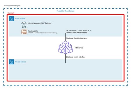
To deploy an F5XC Customer Edge (CE) in SMSv2 mode with the help of automation, it is necessary to follow the three main steps below: Verify the prerequisites at the technical architecture level for the environment in which the CE will be deployed (public cloud or datacenter/private cloud) Create the necessary objects at the F5XC platform level Deploy the CE instance in the target environment We will provide more details for all the steps as well as the simplest Terraform skeleton code to deploy an F5XC CE in the main cloud environments (AWS, GCP and Azure). Step 1: verification of architecture prerequisites To be deployed, a CE must have an interface (which is and will always be its default interface) that has Internet access. This access is necessary to perform the installation steps and provide the "control plane" part to the CE. The name of this interface will be referred to as « Site Local Outside or SLO ». This Internet access can be provided in several ways: "Cloud provider" type site: Public IP address directly on the interface Private IP address on the interface and use of a NAT Gateway as default route Private IP address on the interface and use of a security appliance (firewall type, for example) as default route Private IP address on the interface and use of an explicit proxy Datacenter or "private cloud" type site: Private IP address on the interface and use of a security appliance (firewall type, for example) or router as default route Private IP address on the interface and use of an explicit proxy Furthermore, public IP addresses on the interface and "direct" routing to Internet It is highly recommended (not to say required) to add at least a second interface during the site first deployment. Because depending on the infrastructure (for example, GCP) it is not possible to add network interfaces after the creation of the VM. Even on platforms where adding a network interface is possible, a reboot of the F5XC CE is needed. An F5XC SMSv2 CE can have up to eight interfaces overall. Additional interfaces are (most of the time) used as “Site Local Inside or SLI” interfaces or "Segment interfaces" (that specific part will be covered in another article). Basic CE matrix flow. Interface Direction and protocols Use case / purpose SLO Egress – TCP 53 (DNS), TCP 443 (HTTPS), UDP 53 (DNS), UDP 123 (NTP), UDP 4500 (IPSEC) Registration, software download and upgrade, VPN tunnels towards F5XC infrastructure for control plane SLO Ingress – None RE / CE use case CE to CE use case by using F5 ADN SLO Ingress – UDP 4500 Site Mesh Group for direct CE to CE secure connectivity over SLO interface (no usage of F5 ADN) SLO Ingress – TCP 80 (HTTP), TCP 443 (HTTPS) HTTP/HTTPS LoadBalancer on the CE for WAAP use cases SLI Egress – Depends on the use case / application, but if the security constraint permits it, no restriction SLI Ingress – Depends on the use case / application, but if the security constraint permits it, no restriction For advanced details regarding IPs and domains used for: Registration / software upgrade Tunnels establishment towards F5XC infrastructure Please refer to: https://docs.cloud.f5.com/docs-v2/platform/reference/network-cloud-ref#new-secure-mesh-v2-sites Step 2: creation of necessary objects at the F5XC platform level This step will be performed by the Terraform script by: Creating an SMSv2 token Creating an F5XC site of SMSv2 type API certificate and terraform variables First, it is necessary to create an API certificate. Please follow the instructions in our official documentation here: https://docs.cloud.f5.com/docs-v2/administration/how-tos/user-mgmt/Credentials#generate-api-certificate-for-my-credentials or here: https://docs.cloud.f5.com/docs-v2/administration/how-tos/user-mgmt/Credentials#generate-api-certificate-for-service-credentials Depending on the type of API certificate you want to create and use (user credential or service credential). In the Terraform variables, those are the ones that you need to modify: The “location of the api key” should be the full path where your API P12 file is stored. variable "f5xc_api_p12_file" { type = string description = "F5XC tenant api key" default = "<location of the api key>" } If your F5XC console URL is https://mycompany.console.ves.volterra.io then the value for the f5xc_api_url will be https://mycompany.console.ves.volterra.io/api variable "f5xc_api_url" { type = string default = "https://<tenant name>.console.ves.volterra.io/api" } When using terraform, you will also need to export the P12 certificate password as an environment variable. export VES_P12_PASSWORD=<password of P12 cert> Creation of the SMSv2 token. This is achieved with the following Terraform code and with the “type = 1” parameter. # #F5XC objects creation # resource "volterra_token" "smsv2-token" { depends_on = [volterra_securemesh_site_v2.site] name = "${var.f5xc-ce-site-name}-token" namespace = "system" type = 1 site_name = volterra_securemesh_site_v2.site.name } Creation of the F5XC SMSv2 site. This is achieved with the following Terraform code (example for GCP). This is where you need to configure all the options you want to be applied at site creation. resource "volterra_securemesh_site_v2" "site" { name = format("%s-%s", var.f5xc-ce-site-name, random_id.suffix.hex) namespace = "system" block_all_services = false logs_streaming_disabled = true enable_ha = false labels = { "ves.io/provider" = "ves-io-GCP" } re_select { geo_proximity = true } gcp { not_managed {} } } For instance, if you want to use a corporate proxy and have the CE tunnels passing through the proxy, the following should be added: custom_proxy { enable_re_tunnel = true proxy_ip_address = "10.154.32.254" proxy_port = 8080 } And if you want to force CE to REs connectivity with SSL, the following should be added: tunnel_type = "SITE_TO_SITE_TUNNEL_SSL" Step 3: creation of the CE instance in the target environment This step will be performed by the Terraform script by: Generating a cloud-init file Creating the F5XC site instance in the environment based on the marketplace images or the available F5XC images How to list F5XC available images in Azure: az vm image list --all --publisher f5-networks --offer f5xc_customer_edge --sku f5xccebyol --output table | sort -k4 -V And check in the output, the one with the highest version. x64 f5xc_customer_edge f5-networks f5xccebyol f5-networks:f5xc_customer_edge:f5xccebyol:9.2025.17 9.2025.17 x64 f5xc_customer_edge f5-networks f5xccebyol f5-networks:f5xc_customer_edge:f5xccebyol:2024.40.1 2024.40.1 x64 f5xc_customer_edge f5-networks f5xccebyol f5-networks:f5xc_customer_edge:f5xccebyol:2024.40.2 2024.40.2 x64 f5xc_customer_edge f5-networks f5xccebyol f5-networks:f5xc_customer_edge:f5xccebyol:2024.44.1 2024.44.1 x64 f5xc_customer_edge f5-networks f5xccebyol_2 f5-networks:f5xc_customer_edge:f5xccebyol_2:2024.44.2 2024.44.2 Architecture Offer Publisher Sku Urn Version -------------- ------------------ ----------- ------------ ----------------------------------------------------- --------- We are going to re-use some of the parameters in the Terraform script, to instruct the Terraform code which image it should use. source_image_reference { publisher = "f5-networks" offer = "f5xc_customer_edge" sku = "f5xccebyol" version = "9.2025.17" } Also, for Azure, it’s needed to accept the legal terms of the F5XC CE image. This needs to be performed only once by running the following commands: Select the Azure subscription in which you are planning to deploy the F5XC CE: az account set -s <subscription-id> Accept the terms and conditions for the F5XC CE for this subscription: az vm image terms accept --publisher f5-networks --offer f5xc_customer_edge --plan f5xccebyol How to list F5XC available images in GCP: gcloud compute images list --project=f5-7626-networks-public --filter="name~'f5xc-ce'" --sort-by=~creationTimestamp --format="table(name,creationTimestamp)" And check in the output, the one with the highest version. NAME CREATION_TIMESTAMP f5xc-ce-crt-20250701-0123 2025-07-09T02:15:08.352-07:00 f5xc-cecrt-20250701-0099-9 2025-07-02T01:32:40.154-07:00 f5xc-ce-202505151709081 2025-06-25T22:31:23.295-07:00 How to list F5XC available images in AWS: aws ec2 describe-images \ --region eu-west-3 \ --filters "Name=name,Values=*f5xc-ce*" \ --query "reverse(sort_by(Images, &CreationDate))[*].{ImageId:ImageId,Name:Name,CreationDate:CreationDate}" \ --output table And check in the output, the ami with the latest creation date. Also, for AWS, it’s needed to accept the legal terms of the F5XC CE image. This needs to be performed only once. Go to this page in your AWS Console Then select "View purchase options" and then select "Subscribe". Putting everything together: Global overview We are going to use Azure as the target environment to deploy the F5XC CE. The CE will be deployed with two NICs, the SLO being in a public subnet and a public IP will be attached to the NIC. We assume that all the prerequisites from step 1 are met. Terraform skeleton for Azure is available here: https://github.com/veysph/Prod-TF/ It's not intended to be the perfect thing, just an example of the minimum basic things to deploy an F5XC SMSv2 CE with automation. Changes and enhancements based on the different needs you might have are more than welcome. It's really intended to be flexible and not too strict. Structure of the terraform directory: provider.tf contains everything that is related to the needed providers variables.tf contains all the variables used in the terraform files f5xc_sites.tf contains everything that is related to the F5XC objects creation main.tf contains everything to start the F5XC CE in the target environment Deployment Make all the relevant changes in variables.tf. Don't forget to export your P12 password as an environment variable (see Step 2, API certificate and terraform variables)! Then run, terraform init terraform plan terraform apply Should everything be correct at each step, you should get a CE object in the F5XC console, under Multi-Cloud Network Connect --> Manage --> Site Management --> Secure Mesh Sites v2700Views5likes1Comment