openshift
22 TopicsThree Things I've Learned Recently While Deploying F5 CIS on OpenShift
Not every CIS deployment issue is actually a CIS issue. This article walks through three lessons learned from recent OpenShift deployments where the real culprit turned out to be NetworkPolicies, image selection, and version management rather than the controller itself.83Views3likes0Comments
Automating TLS Certificates in Kubernetes with cert-manager and F5 Distributed Cloud DNS
Introduction If you run workloads in Kubernetes or Open Shift, you've almost certainly dealt with TLS certificates. You need them everywhere — Ingress controllers, internal services, mutual TLS between microservices, and API gateways. Managing them by hand is error-prone and doesn't scale: certificates expire silently, rotation is forgotten, and the person who originally created the wildcard cert is now working somewhere else. cert-manager solves this elegantly. It's a Kubernetes-native certificate controller that automates the issuance, renewal, and management of TLS certificates. It speaks ACME — the same protocol Let's Encrypt uses — but ACME is a standard, not a Let's Encrypt exclusive. You can point cert-manager at: Let's Encrypt (free, public, widely trusted) ZeroSSL, Buypass, Google Trust Services — other public CAs supporting ACME Step CA / HashiCorp Vault / Smallstep — for private PKI running inside your infrastructure Any commercial CA that has implemented an ACME endpoint This means the same workflow, the same Kubernetes manifests, and the same tooling can back both your public-facing services and your internal, corporate-signed certificates. One operator to rule them all. Why DNS-01 Challenge? ACME offers multiple ways to prove you own a domain. The most common is the HTTP-01 challenge, where the ACME server checks a well-known URL on your domain. It works well, but has limitations: The endpoint must be publicly reachable on port 80 It cannot issue wildcard certificates (*.example.com) The DNS-01 challenge takes a different approach: cert-manager (via a solver webhook) creates a _acme-challenge.example.com TXT record in your DNS zone. The ACME server checks for this record. Once verified, the TXT record is cleaned up automatically. Benefits: Works behind firewalls — no inbound HTTP needed Supports wildcard certificates — a single *.example.com certificate covers all subdomains Fully automated — the webhook handles record creation and deletion If your DNS is managed by F5 Distributed Cloud (F5 XC), you can now wire this entire flow together with the open-source cert-manager-webhook-f5xc solver. Architecture Overview Here's what happens when cert-manager issues a certificate using the F5 XC webhook: Developer applies Certificate manifest ▼ cert-manager creates Order + Challenge ▼ cert-manager calls webhook (DNS-01 solver) ▼ Webhook calls F5 XC DNS API → Creates TXT record: _acme-challenge.example.com ▼ ACME server (Let's Encrypt / other) validates the TXT record ▼ Webhook cleans up the TXT record ▼ cert-manager stores the issued certificate in a Kubernetes Secret The webhook runs as a standard Kubernetes Deployment inside your cluster, registered with cert-manager via a ValidatingWebhookConfiguration. It receives solver calls from cert-manager and translates them into F5 XC DNS API calls using an API token you provide as a Kubernetes Secret. Prerequisites Before we start, make sure you have the following in place: A Kubernetes cluster (1.21+) cert-manager installed (v1.14+) kubectl apply -f https://github.com/cert-manager/cert-manager/releases/latest/download/cert-manager.yaml Helm 3.8+ An F5 Distributed Cloud tenant with DNS management enabled Your domain's DNS zone managed in F5 XC F5 XC credentials for DNS API access — either an API Token or a Client Certificate (P12); see Step 1 below for details Least privilege note: The service account or user whose credentials you use must have permission to manage DNS records. As of the time of writing, the built-in role f5xc-dns-management-admin is sufficient. Avoid using tenant-admin or other overly broad roles — the webhook only needs to create and delete TXT records in your DNS zone. Step 1: Prepare F5 XC Credentials The webhook supports two authentication methods against the F5 XC DNS API: an API Token or a Client Certificate (P12). Both are stored as a Kubernetes Secret in the cert-manager namespace. Obtaining credentials in F5 XC Console Regardless of which method you choose, the service account must have sufficient permissions to manage DNS records. Follow the least-privilege principle: In the F5 XC Console, navigate to Account Settings → Administration. Create a dedicated service credential under IAM and assign it the f5xc-dns-management-admin role in the system namespace — this is the minimum required role as of the time of writing and grants access to DNS Zone Management without unnecessary privileges elsewhere in the tenant. Or use an existing account privileges under Personal Management credentials. Generate the credentials of your preferred type (API Token or API Certificate) Option A: API Token (simpler, recommended for most setups) Take the API Token obtained from the F5XC console and use it with the following command kubectl create secret generic f5xc-api-token \ --namespace cert-manager \ --from-literal=token=<YOUR_F5XC_API_TOKEN> Option B: Client Certificate (P12) F5 XC also supports certificate-based authentication using a P12 (PKCS#12) client certificate, which may be preferred in environments. Use the certificate and password generated in the previous step and store it as a Secret: kubectl create secret generic f5xc-client-cert \ --namespace cert-manager \ --from-file=certificate.p12=<PATH_TO_YOUR.p12> \ --from-literal=password=<P12_PASSWORD> Refer to the webhook documentation for the exact certificateSecretRef fields to use in the solver config when choosing this method. Verify the secret was created: kubectl get secret f5xc-api-token -n cert-manager Step 2: Install the Webhook via Helm The chart is published as an OCI artifact on GitHub Container Registry. Install it into the cert-manager namespace: helm install cert-manager-webhook-f5xc \ oci://ghcr.io/wenkow/charts/cert-manager-webhook-f5xc \ --namespace cert-managerbaba Check the rollout: kubectl rollout status \ deployment cert-manager-webhook-f5xc \ -n cert-manager kubectl get pods -n cert-manager Step 3: Configure a ClusterIssuer A ClusterIssuer tells cert-manager which ACME server to use and how to solve challenges. Here we're pointing it at Let's Encrypt production and configuring the F5 XC DNS-01 solver. Note on groupName: The field appears twice in the YAML below and serves different purposes. At the webhook level, it's a fixed identifier (acme.f5xc.io) that tells cert-manager which registered webhook to call. Inside config, it's the RRSet group name within your F5 XC DNS zone — a logical container for DNS records created by the webhook. You can choose any name; F5 XC will create the group if it doesn't exist. clusterissuer.yaml: apiVersion: cert-manager.io/v1 kind: ClusterIssuer metadata: name: letsencrypt-f5xc-prod spec: acme: email: [email protected] server: https://acme-v02.api.letsencrypt.org/directory privateKeySecretRef: name: letsencrypt-f5xc-prod-account-key solvers: - dns01: webhook: # Fixed identifier — tells cert-manager which webhook to call groupName: acme.f5xc.io solverName: f5xc config: # Your F5 XC tenant name (subdomain part of your console URL) tenantName: my-tenant # RRSet group name in F5 XC DNS zone groupName: "cert-manager" # ttl: 120 # optional, default is 120 seconds apiTokenSecretRef: name: f5xc-api-token key: token # If using certificate-based auth instead of a token, replace # apiTokenSecretRef with certificateSecretRef — see webhook docs. Apply it: kubectl apply -f clusterissuer.yaml Verify it's ready: kubectl get clusterissuer letsencrypt-f5xc-prod Step 4: Request a Certificate Now the fun part. Create a Certificate resource. Note that we're requesting both the apex domain and a wildcard — something that's only possible with DNS-01. certificate.yaml: apiVersion: cert-manager.io/v1 kind: Certificate metadata: name: example-tls namespace: default spec: secretName: example-tls issuerRef: name: letsencrypt-f5xc-prod kind: ClusterIssuer dnsNames: - example.com - "*.example.com" Apply it: kubectl apply -f certificate.yaml Step 5: Watch the Certificate Lifecycle This is where it gets satisfying to watch. cert-manager creates an Order, which spawns one or more Challenge objects. Each Challenge triggers the F5 XC webhook to create a DNS TXT record. Watch Certificate status kubectl get certificate example-tls -n default -w Inspect the Order kubectl get orders -n default kubectl describe order example-tls-1-3552197254 -n default Status: Authorizations: Challenges: Token: <token> Type: dns-01 URL: https://acme-v02.api.letsencrypt.org/acme/chall/... Identifier: example.com Initial State: valid URL: https://acme-v02.api.letsencrypt.org/acme/authz/... Wildcard: true Challenges: Token: <token> Type: dns-01 URL: https://acme-v02.api.letsencrypt.org/acme/chall/... Identifier: example.com Initial State: valid URL: https://acme-v02.api.letsencrypt.org/acme/authz/... Wildcard: false Certificate: REDACTED Finalize URL: https://acme-v02.api.letsencrypt.org/acme/finalize/... State: valid URL: https://acme-v02.api.letsencrypt.org/acme/order/... Events: Type Reason Age From Message ---- ------ ---- ---- ------- Normal Complete 8m37s cert-manager-orders Order completed successfully Inspect the Challenges before it's done kubectl get challenges -n default kubectl describe challenge example-tls-<1234567890> -n default Verify the Issued Certificate kubectl get secret example-tls -n default -o jsonpath='{.data.tls\.crt}' \ | base64 -d | openssl x509 -noout -text | grep -E "Subject:|DNS:|Not After" Not After : Aug 19 19:22:31 2026 GMT Subject: CN = example.com DNS:*.example.com, DNS:example.com Both the apex domain and the wildcard are covered by a single certificate. Using a Custom or Internal ACME Server One of the most powerful aspects of this setup is that the ACME server is completely configurable. If you run an internal CA — for example HashiCorp Vault with the ACME secrets engine, or Step CA — just change the server field in your ClusterIssuer: spec: acme: email: [email protected] server: https://vault.internal.example.com/v1/pki/acme/directory # or # server: https://step-ca.internal.example.com/acme/acme/directory The webhook doesn't care which ACME server you use — it only handles the DNS side of the challenge. This makes the setup equally useful for: Internet-facing services using Let's Encrypt Internal services using a corporate CA Mixed environments where different ClusterIssuer objects point to different CAs, all sharing the same F5 XC DNS solver Troubleshooting Tips Challenge stays in pending for a long time Check the webhook logs for API errors: kubectl logs -n cert-manager -l app=cert-manager-webhook-f5xc --tail=50 READY: False on ClusterIssuer Usually means cert-manager couldn't register an ACME account. Check that the email field is valid and the ACME server URL is reachable. TXT record not appearing in F5 XC - Verify that the credentials you stored in the Secret have the right DNS permissions. In F5 XC Console, check that the service account has the f5xc-dns-management-admin role (or equivalent). API token permission issues will typically surface as 403 Forbidden errors in the webhook logs. Summary The cert-manager-webhook-f5xc project closes the loop between F5 Distributed Cloud DNS and the Kubernetes-native certificate management ecosystem. With a few manifests and a Helm install, you get: Fully automated certificate issuance and renewal — no manual interventions, no expiry surprises Wildcard certificate support out of the box via DNS-01 ACME provider flexibility — works with Let's Encrypt, commercial CAs, or your internal PKI Clean Kubernetes-native UX — certificates are just resources; the entire lifecycle is observable with standard kubectl commands The webhook is open source, available on GitHub and packaged on Artifact Hub. Contributions and feedback are welcome. Related Resources cert-manager documentation cert-manager DNS01 webhook reference F5 Distributed Cloud DNS Management docs GitHub: Wenkow/cert-manager-webhook-f5xc Artifact Hub: cert-manager-webhook-f5xc277Views2likes1CommentDeploying the F5 AI Security Certified OpenShift Operator: A Validated Playbook
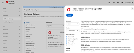
Introduction As enterprises race to deploy Large Language Models (LLMs) in production, securing AI workloads has become as critical as securing traditional applications. The F5 AI Security Operator installs two products on your cluster — F5 AI Guardrails and F5 AI Red Team — both powered by CalypsoAI. Together they provide inline prompt/response scanning, policy enforcement, and adversarial red-team testing, all running natively on your own OpenShift cluster. This article is a validated deployment runbook for F5 AI Security on OpenShift (version 4.20.14) with NVIDIA GPU nodes. It is based on the official Red Hat Operator installation baseline, in a real lab deployment on a 3×A40 GPU cluster. If you follow these steps in order, you will end up with a fully functional AI Security stack, avoiding the most common pitfalls along the way. What Gets Deployed F5 AI Security consists of four main components, each running in its own OpenShift namespace: Component Namespace Role Moderator + PostgreSQL cai-moderator Web UI, API gateway, policy management, and backing database Prefect Server + Worker prefect Workflow orchestration for scans and red-team runs AI Guardrails Scanner cai-scanner Inline scanning against your OpenAI-compatible LLM endpoint AI Red Team Worker cai-redteam GPU-backed adversarial testing; reports results to Moderator via Prefect The Moderator is CPU-only. The Scanner and Red Team Worker can leverage GPUs depending on the policies and models you configure. Infrastructure Requirements Before you begin, verify your cluster meets these minimums: CPU / Control Node 16 vCPUs, 32 GiB RAM, x86_64, 100 GiB persistent storage Worker Nodes (per GPU-enabled component) 4 vCPUs, 16 GiB RAM (32 GiB recommended for Red Team), 100 GiB storage GPU Nodes AI Guardrails: CUDA-compatible GPU, minimum 24 GB VRAM, 100 GiB storage AI Red Team: CUDA-compatible GPU, minimum 48 GB VRAM, 200 GiB storage GPU must NOT be shared with other workloads Verify your cluster: # Check nodes oc get nodes -o wide # Check GPU allocatable resources oc get node -o jsonpath='{range .items[*]}{.metadata.name}{"\t"}{.status.allocatable.nvidia\.com/gpu}{"\n"}{end}' # Check available storage classes oc get storageclass NAME PROVISIONER RECLAIMPOLICY VOLUMEBINDINGMODE ALLOWVOLUMEEXPANSION AGE lvms-vg1 (default) topolvm.io Delete WaitForFirstConsumer true 15d Step 1 — Install Prerequisites 1.1 Node Feature Discovery (NFD) Operator NFD labels your nodes with hardware capabilities, which NVIDIA GPU Operator relies on to target the right nodes. OpenShift Console → Ecosystem → Software Catalog → Search Node Feature Discovery Operator → Install After installation: Installed Operators → Node Feature Discovery → Create NodeFeatureDiscovery → Accept defaults Verify: oc get pods -n openshift-nfd oc get node --show-labels | grep feature.node.kubernetes.io || true 1.2 NVIDIA GPU Operator OpenShift Console → Ecosystem → Software Catalog → Search GPU Operator → Install After installation: Installed Operators → NVIDIA GPU Operator → Create ClusterPolicy → Accept defaults Verify: oc get pods -n nvidia-gpu-operator oc describe node <gpu-node> | grep -i nvidia nvidia-smi</gpu-node> Step 2 — Install F5 AI Security Operator Prerequisites: You will need registry credentials and a valid license from the F5 AI Security team before proceeding. Contact F5 Sales: https://www.f5.com/products/get-f5 2.1 Create the Namespace and Pull Secret export DOCKER_USERNAME='<registry-username>' export DOCKER_PASSWORD='<registry-password>' export DOCKER_EMAIL='<your-email>' oc new-project f5-ai-sec oc create secret docker-registry regcred \ -n f5-ai-sec \ --docker-username=$DOCKER_USERNAME \ --docker-password=$DOCKER_PASSWORD \ --docker-email=$DOCKER_EMAIL</your-email></registry-password></registry-username> 2.2 Install from OperatorHub OpenShift Console → Ecosystem → Software Catalog → Search F5 AI Security Operator → Install into namespace f5-ai-sec Verify your F5 AI Security Operator: # Verify the controller-manager pod is Running oc -n f5-ai-sec get pods # NAME READY STATUS RESTARTS AGE # controller-manager-6f784bd96d-z6sbh 1/1 Running 1 43s # Verify the CSV reached Succeeded phase oc -n f5-ai-sec get csv # NAME DISPLAY VERSION PHASE # f5-ai-security-operator.v0.4.3 F5 Ai Security Operator 0.4.3 Succeeded # Verify the CRD is registered oc -n f5-ai-sec get crd | grep ai.security.f5.com # securityoperators.ai.security.f5.com 2.3 Deploy the SecurityOperator Custom Resource After installation: Installed Operators → F5 AI Security Operator → Create SecurityOperator Choose YAML and copy the below Custom Resource Template in there, changing select values to match your installation. apiVersion: ai.security.f5.com/v1alpha1 kind: SecurityOperator metadata: name: security-operator-demo namespace: f5-ai-sec spec: registryAuth: existingSecret: "regcred" # Internal PostgreSQL — convenient for labs, not recommended for production postgresql: enabled: true values: postgresql: auth: password: "pass" jobManager: enabled: true moderator: enabled: true values: env: CAI_MODERATOR_BASE_URL: https://<your-hostname> secrets: CAI_MODERATOR_DB_ADMIN_PASSWORD: "pass" CAI_MODERATOR_DEFAULT_LICENSE: "<valid_license_from_f5>" scanner: enabled: true redTeam: enabled: true</valid_license_from_f5></your-hostname> Key values to customize: Field What to set CAI_MODERATOR_BASE_URL Your cluster's public hostname for the UI (e.g., https://aisec.apps.mycluster.example.com ) CAI_MODERATOR_DEFAULT_LICENSE License string provided by F5 CAI_MODERATOR_DB_ADMIN_PASSWORD DB password — must match the value set in the PostgreSQL block For external PostgreSQL (recommended for production), replace the postgresql block with: moderator: values: env: CAI_MODERATOR_DB_HOST: <my-external-db-hostname> secrets: CAI_MODERATOR_DB_ADMIN_PASSWORD: <my-external-db-password></my-external-db-password></my-external-db-hostname> Verify your F5 AI Security Operator: oc -n f5-ai-sec get securityoperator oc -n f5-ai-sec get securityoperator security-operator-demo -o yaml | sed -n '/status:/,$p' Step 3 — Required OpenShift Configuration This is where most deployments hit problems. OpenShift's default restricted Security Context Constraint (SCC) blocks these containers from running. You must explicitly grant anyuid to each service account. 3.1 Apply SCC Policies oc adm policy add-scc-to-user anyuid -z cai-moderator-sa -n cai-moderator oc adm policy add-scc-to-user anyuid -z default -n cai-moderator oc adm policy add-scc-to-user anyuid -z default -n prefect oc adm policy add-scc-to-user anyuid -z prefect-server -n prefect oc adm policy add-scc-to-user anyuid -z prefect-worker -n prefect oc adm policy add-scc-to-user anyuid -z cai-scanner -n cai-scanner oc adm policy add-scc-to-user anyuid -z cai-redteam-worker -n cai-redteam 3.2 Force PostgreSQL to Restart (if Stuck at 0/1) If PostgreSQL was stuck before the SCC was applied, bounce it manually: oc -n cai-moderator scale sts/cai-moderator-postgres-cai-postgresql --replicas=0 oc -n cai-moderator scale sts/cai-moderator-postgres-cai-postgresql --replicas=1 3.3 Restart All Components oc -n cai-moderator rollout restart deploy oc -n prefect rollout restart deploy oc -n cai-scanner rollout restart deploy oc -n cai-redteam rollout restart deploy 3.4 Verify ➜ oc -n cai-moderator get statefulset NAME READY AGE cai-moderator-postgres-cai-postgresql 1/1 3d4h ➜ oc -n cai-moderator get pods | grep postgres cai-moderator-postgres-cai-postgresql-0 1/1 Running 0 3d4h ➜ oc -n cai-moderator get pods | grep cai-moderator cai-moderator-75c47fc9db-sl8t2 1/1 Running 0 3d4h cai-moderator-postgres-cai-postgresql-0 1/1 Running 0 3d4h ➜ oc -n cai-moderator get svc NAME TYPE CLUSTER-IP EXTERNAL-IP PORT(S) AGE cai-moderator ClusterIP 172.30.123.197 <none> 5500/TCP,8080/TCP 3d4h cai-moderator-headless ClusterIP None <none> 8080/TCP 3d4h cai-moderator-postgres-postgresql ClusterIP None <none> 5432/TCP 3d4h ➜ oc -n cai-moderator get endpoints Warning: v1 Endpoints is deprecated in v1.33+; use discovery.k8s.io/v1 EndpointSlice NAME ENDPOINTS AGE cai-moderator 10.130.0.139:8080,10.130.0.139:5500 3d4h cai-moderator-headless 10.130.0.139:8080 3d4h cai-moderator-postgres-postgresql 10.128.0.177:5432 3d4h</none></none></none> Step 4 — Create OpenShift Routes (Required for UI Access) The Moderator exposes two ports that must be routed separately: port 5500 for the UI and port 8080 for the /auth path. Skipping the auth route is the most common cause of the blank/black page issue. # UI route oc -n cai-moderator create route edge cai-moderator-ui \ --service=cai-moderator \ --port=5500 \ --hostname=<your-hostname> \ --path=/ # Auth route — required, or the UI will render blank oc -n cai-moderator create route edge cai-moderator-auth \ --service=cai-moderator \ --port=8080 \ --hostname=<your-hostname> \ --path=/auth</your-hostname></your-hostname> Verify all pods are running: oc get pods -n cai-moderator oc get pods -n cai-scanner oc get pods -n cai-redteam oc get pods -n prefect Access the UI Open https:// in a browser. Log in with the default credentials: admin / pass Log in and update the admin email address immediately. You should be able to log in successfully and see the Guardrails dashboard. Step 5 — Grant Prefect Worker Cluster-scope RBAC The Prefect worker watches Kubernetes Pods and Jobs at cluster scope to monitor scan and red-team workflow execution. Without this RBAC, prefect-worker fills its logs with 403 Forbidden errors. The Guardrails UI still loads, but scheduled workflows and Red Team runs will fail silently. # ClusterRole: allow prefect-worker to list/watch pods, jobs, and events cluster-wide oc apply -f - <<'YAML' apiVersion: rbac.authorization.k8s.io/v1 kind: ClusterRole metadata: name: prefect-worker-watch-cluster rules: - apiGroups: ["batch"] resources: ["jobs"] verbs: ["get","list","watch"] - apiGroups: [""] resources: ["pods","pods/log","events"] verbs: ["get","list","watch"] YAML # ClusterRoleBinding: bind to the prefect-worker ServiceAccount oc apply -f - <<'YAML' apiVersion: rbac.authorization.k8s.io/v1 kind: ClusterRoleBinding metadata: name: prefect-worker-watch-cluster subjects: - kind: ServiceAccount name: prefect-worker namespace: prefect roleRef: apiGroup: rbac.authorization.k8s.io kind: ClusterRole name: prefect-worker-watch-cluster YAML # Restart to pick up the new permissions oc -n prefect rollout restart deploy/prefect-worker Verify RBAC errors are gone: oc -n prefect logs deploy/prefect-worker --tail=200 \ | egrep -i 'forbidden|rbac|permission|denied' \ || echo "OK: no RBAC errors detected" oc get clusterrolebinding prefect-worker-watch-cluster LlamaStack Integration F5 AI Security works alongside any OpenAI-compatible LLM inference endpoint. In our lab we pair it with LlamaStack running a quantized Llama 3.2 model on the same OpenShift cluster — F5 AI Guardrails then scans every prompt and response inline before it reaches your application. A dedicated follow-up post will walk through the full LlamaStack deployment and end-to-end integration in detail. Stay tuned. Summary Deploying F5 AI Security on OpenShift is straightforward once you know the OpenShift-specific friction points: SCC policies, the dual-route requirement, and the Prefect cluster-scope RBAC. Following this runbook in sequence — prerequisites, operator install, SCC grants, routes, Prefect RBAC — gets you to a fully operational AI guardrailing stack in a single pass. If you run into anything not covered here, drop a comment below. Tested on: OpenShift 4.20.14 · F5 AI Security Operator v0.4.3 · NVIDIA A40 GPUs · LlamaStack with Llama-3.2-1B-Instruct-quantized.w8a8 Additional Resources F5 AI Security Operator — Red Hat Catalog1.2KViews1like0CommentsF5 Container Ingress Services (CIS) deployment using Cilium CNI and static routes
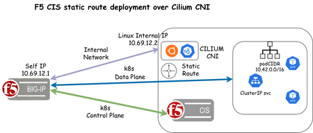
F5 Container Ingress Services (CIS) supports static route configuration to enable direct routing from F5 BIG-IP to Kubernetes/OpenShift Pods as an alternative to VXLAN tunnels. Static routes are enabled in the F5 CIS CLI/Helm yaml manifest using the argument --static-routing-mode=true. In this article, we will use Cilium as the Container Network Interface (CNI) and configure static routes for an NGINX deployment For initial configuration of the BIG-IP, including AS3 installation, please see https://clouddocs.f5.com/products/extensions/f5-appsvcs-extension/latest/userguide/installation.html and https://clouddocs.f5.com/containers/latest/userguide/kubernetes/#cis-installation The first step is to install Cilium CNI using the steps below on Linux host: CILIUM_CLI_VERSION=$(curl -s https://raw.githubusercontent.com/cilium/cilium-cli/main/stable.txt) CLI_ARCH=amd64 if [ "$(uname -m)" = "aarch64" ]; then CLI_ARCH=arm64; fi curl -L --fail --remote-name-all https://github.com/cilium/cilium-cli/releases/download/${CILIUM_CLI_VERSION}/cilium-linux-${CLI_ARCH}.tar.gz{,.sha256sum} sha256sum --check cilium-linux-${CLI_ARCH}.tar.gz.sha256sum sudo tar xzvfC cilium-linux-${CLI_ARCH}.tar.gz /usr/local/bin rm cilium-linux-${CLI_ARCH}.tar.gz{,.sha256sum} cilium install --version 1.18.5 cilium status cilium status --wait root@ciliumk8s-ubuntu-server:~# cilium status --wait /¯¯\ /¯¯\__/¯¯\ Cilium: OK \__/¯¯\__/ Operator: OK /¯¯\__/¯¯\ Envoy DaemonSet: OK \__/¯¯\__/ Hubble Relay: disabled \__/ ClusterMesh: disabled DaemonSet cilium Desired: 1, Ready: 1/1, Available: 1/1 DaemonSet cilium-envoy Desired: 1, Ready: 1/1, Available: 1/1 Deployment cilium-operator Desired: 1, Ready: 1/1, Available: 1/1 Containers: cilium Running: 1 cilium-envoy Running: 1 cilium-operator Running: 1 clustermesh-apiserver hubble-relay Cluster Pods: 6/6 managed by Cilium Helm chart version: 1.18.3 Image versions cilium quay.io/cilium/cilium:v1.18.3@sha256:5649db451c88d928ea585514746d50d91e6210801b300c897283ea319d68de15: 1 cilium-envoy quay.io/cilium/cilium-envoy:v1.34.10-1761014632-c360e8557eb41011dfb5210f8fb53fed6c0b3222@sha256:ca76eb4e9812d114c7f43215a742c00b8bf41200992af0d21b5561d46156fd15: 1 cilium-operator quay.io/cilium/operator-generic:v1.18.3@sha256:b5a0138e1a38e4437c5215257ff4e35373619501f4877dbaf92c89ecfad81797: 1 cilium connectivity test root@ciliumk8s-ubuntu-server:~# cilium connectivity test ℹ️ Monitor aggregation detected, will skip some flow validation steps ✨ [default] Creating namespace cilium-test-1 for connectivity check... ✨ [default] Deploying echo-same-node service... ✨ [default] Deploying DNS test server configmap... ✨ [default] Deploying same-node deployment... ✨ [default] Deploying client deployment... ✨ [default] Deploying client2 deployment... ✨ [default] Deploying ccnp deployment... ⌛ [default] Waiting for deployment cilium-test-1/client to become ready... ⌛ [default] Waiting for deployment cilium-test-1/client2 to become ready... ⌛ [default] Waiting for deployment cilium-test-1/echo-same-node to become ready... ⌛ [default] Waiting for deployment cilium-test-ccnp1/client-ccnp to become ready... ⌛ [default] Waiting for deployment cilium-test-ccnp2/client-ccnp to become ready... ⌛ [default] Waiting for pod cilium-test-1/client-645b68dcf7-s5mdb to reach DNS server on cilium-test-1/echo-same-node-f5b8d454c-qkgq9 pod... ⌛ [default] Waiting for pod cilium-test-1/client2-66475877c6-cw7f5 to reach DNS server on cilium-test-1/echo-same-node-f5b8d454c-qkgq9 pod... ⌛ [default] Waiting for pod cilium-test-1/client-645b68dcf7-s5mdb to reach default/kubernetes service... ⌛ [default] Waiting for pod cilium-test-1/client2-66475877c6-cw7f5 to reach default/kubernetes service... ⌛ [default] Waiting for Service cilium-test-1/echo-same-node to become ready... ⌛ [default] Waiting for Service cilium-test-1/echo-same-node to be synchronized by Cilium pod kube-system/cilium-lxjxf ⌛ [default] Waiting for NodePort 10.69.12.2:32046 (cilium-test-1/echo-same-node) to become ready... 🔭 Enabling Hubble telescope... ⚠️ Unable to contact Hubble Relay, disabling Hubble telescope and flow validation: rpc error: code = Unavailable desc = connection error: desc = "transport: Error while dialing: dial tcp 127.0.0.1:4245: connect: connection refused" ℹ️ Expose Relay locally with: cilium hubble enable cilium hubble port-forward& ℹ️ Cilium version: 1.18.3 🏃[cilium-test-1] Running 126 tests ... [=] [cilium-test-1] Test [no-policies] [1/126] .................... [=] [cilium-test-1] Skipping test [no-policies-from-outside] [2/126] (skipped by condition) [=] [cilium-test-1] Test [no-policies-extra] [3/126] <- snip -> For this article, we will install k3s with Cilium CNI root@ciliumk8s-ubuntu-server:~# curl -sfL https://get.k3s.io | sh -s - --flannel-backend=none --disable-kube-proxy --disable servicelb --disable-network-policy --disable traefik --cluster-init --node-ip=10.69.12.2 --cluster-cidr=10.42.0.0/16 root@ciliumk8s-ubuntu-server:~# mkdir -p $HOME/.kube root@ciliumk8s-ubuntu-server:~# sudo cp -i /etc/rancher/k3s/k3s.yaml $HOME/.kube/config root@ciliumk8s-ubuntu-server:~# sudo chown $(id -u):$(id -g) $HOME/.kube/config root@ciliumk8s-ubuntu-server:~# echo "export KUBECONFIG=$HOME/.kube/config" >> $HOME/.bashrc root@ciliumk8s-ubuntu-server:~# source $HOME/.bashrc API_SERVER_IP=10.69.12.2 API_SERVER_PORT=6443 CLUSTER_ID=1 CLUSTER_NAME=`hostname` POD_CIDR="10.42.0.0/16" root@ciliumk8s-ubuntu-server:~# cilium install --set cluster.id=${CLUSTER_ID} --set cluster.name=${CLUSTER_NAME} --set k8sServiceHost=${API_SERVER_IP} --set k8sServicePort=${API_SERVER_PORT} --set ipam.operator.clusterPoolIPv4PodCIDRList=$POD_CIDR --set kubeProxyReplacement=true --helm-set=operator.replicas=1 root@ciliumk8s-ubuntu-server:~# cilium config view | grep cluster bpf-lb-external-clusterip false cluster-id 1 cluster-name ciliumk8s-ubuntu-server cluster-pool-ipv4-cidr 10.42.0.0/16 cluster-pool-ipv4-mask-size 24 clustermesh-enable-endpoint-sync false clustermesh-enable-mcs-api false ipam cluster-pool max-connected-clusters 255 policy-default-local-cluster false root@ciliumk8s-ubuntu-server:~# cilium status --wait The F5 CIS yaml manifest for deployment using Helm Note that these arguments are required for CIS to leverage static routes static-routing-mode: true orchestration-cni: cilium-k8s We will also be installing custom resources, so this argument is also required 3. custom-resource-mode: true Values yaml manifest for Helm deployment bigip_login_secret: f5-bigip-ctlr-login bigip_secret: create: false username: password: rbac: create: true serviceAccount: # Specifies whether a service account should be created create: true # The name of the service account to use. # If not set and create is true, a name is generated using the fullname template name: k8s-bigip-ctlr # This namespace is where the Controller lives; namespace: kube-system ingressClass: create: true ingressClassName: f5 isDefaultIngressController: true args: # See https://clouddocs.f5.com/containers/latest/userguide/config-parameters.html # NOTE: helm has difficulty with values using `-`; `_` are used for naming # and are replaced with `-` during rendering. # REQUIRED Params bigip_url: X.X.X.S bigip_partition: <BIG-IP_PARTITION> # OPTIONAL PARAMS -- uncomment and provide values for those you wish to use. static-routing-mode: true orchestration-cni: cilium-k8s # verify_interval: # node-poll_interval: # log_level: DEBUG # python_basedir: ~ # VXLAN # openshift_sdn_name: # flannel_name: cilium-vxlan # KUBERNETES # default_ingress_ip: # kubeconfig: # namespaces: ["foo", "bar"] # namespace_label: # node_label_selector: pool_member_type: cluster # resolve_ingress_names: # running_in_cluster: # use_node_internal: # use_secrets: insecure: true custom-resource-mode: true log-as3-response: true as3-validation: true # gtm-bigip-password # gtm-bigip-url # gtm-bigip-username # ipam : true image: # Use the tag to target a specific version of the Controller user: f5networks repo: k8s-bigip-ctlr pullPolicy: Always version: latest # affinity: # nodeAffinity: # requiredDuringSchedulingIgnoredDuringExecution: # nodeSelectorTerms: # - matchExpressions: # - key: kubernetes.io/arch # operator: Exists # securityContext: # runAsUser: 1000 # runAsGroup: 3000 # fsGroup: 2000 # If you want to specify resources, uncomment the following # limits_cpu: 100m # limits_memory: 512Mi # requests_cpu: 100m # requests_memory: 512Mi # Set podSecurityContext for Pod Security Admission and Pod Security Standards # podSecurityContext: # runAsUser: 1000 # runAsGroup: 1000 # privileged: true Installation steps for deploying F5 CIS using helm can be found in this link https://clouddocs.f5.com/containers/latest/userguide/kubernetes/ Once F5 CIS is validated to be up and running, we can now deploy the following application example root@ciliumk8s-ubuntu-server:~# cat application.yaml apiVersion: cis.f5.com/v1 kind: VirtualServer metadata: labels: f5cr: "true" name: goblin-virtual-server namespace: nsgoblin spec: host: goblin.com pools: - path: /green service: svc-nodeport servicePort: 80 - path: /harry service: svc-nodeport servicePort: 80 virtualServerAddress: X.X.X.X --- apiVersion: apps/v1 kind: Deployment metadata: name: goblin-backend namespace: nsgoblin spec: replicas: 2 selector: matchLabels: app: goblin-backend template: metadata: labels: app: goblin-backend spec: containers: - name: goblin-backend image: nginx:latest ports: - containerPort: 80 --- apiVersion: v1 kind: Service metadata: name: svc-nodeport namespace: nsgoblin spec: selector: app: goblin-backend ports: - port: 80 targetPort: 80 type: ClusterIP k apply -f application.yaml We can now verify the k8s pods are created. Then we will create a sample html page to test access to the backend NGINX pod root@ciliumk8s-ubuntu-server:~# k -n nsgoblin get po -owide NAME READY STATUS RESTARTS AGE IP NODE NOMINATED NODE READINESS GATES goblin-backend-7485b6dcdf-d5t48 1/1 Running 0 6d2h 10.42.0.70 ciliumk8s-ubuntu-server <none> <none> goblin-backend-7485b6dcdf-pt7hx 1/1 Running 0 6d2h 10.42.0.97 ciliumk8s-ubuntu-server <none> <none> root@ciliumk8s-ubuntu-server:~# k -n nsgoblin exec -it po/goblin-backend-7485b6dcdf-pt7hx -- /bin/sh # cat > green <<'EOF' <!DOCTYPE html> > > <html> > <head> <title>Green Goblin</title> <style> body { background-color: #4CAF50; color: white; text-align: center; padding: 50px; } h1 { font-size: 3em; } > > > > > </style> </head> <body> <h1>I am the green goblin!</h1> <p>Access me at /green</p> </body> </html> > > > > > > > EOF root@ciliumk8s-ubuntu-server:~# k -n nsgoblin exec -it goblin-backend-7485b6dcdf-d5t48 -- /bin/sh # cat > green <<'EOF' > <!DOCTYPE html> <html> <head> <title>Green Goblin</title> <style> body { background-color: #4CAF50; color: white; text-align: center; padding: 50px; } h1 { font-size: 3em; } </style> > </head> <body> <h1>I am the green goblin!</h1> <p>Access me at /green</p> </body> </html> EOF> > > > > > > > > > > > > We can now validate the pools are created on the F5 BIG-IP root@(ciliumk8s-bigip)(cfg-sync Standalone)(Active)(/kubernetes/Shared)(tmos)# list ltm pool all ltm pool svc_nodeport_80_nsgoblin_goblin_com_green { description "crd_10_69_12_40_80 loadbalances this pool" members { /kubernetes/10.42.0.70:http { address 10.42.0.70 } /kubernetes/10.42.0.97:http { address 10.42.0.97 } } min-active-members 1 partition kubernetes } ltm pool svc_nodeport_80_nsgoblin_goblin_com_harry { description "crd_10_69_12_40_80 loadbalances this pool" members { /kubernetes/10.42.0.70:http { address 10.42.0.70 } /kubernetes/10.42.0.97:http { address 10.42.0.97 } } min-active-members 1 partition kubernetes } root@(ciliumk8s-bigip)(cfg-sync Standalone)(Active)(/kubernetes/Shared)(tmos)# list ltm virtual crd_10_69_12_40_80 ltm virtual crd_10_69_12_40_80 { creation-time 2025-12-22:10:10:37 description Shared destination /kubernetes/10.69.12.40:http ip-protocol tcp last-modified-time 2025-12-22:10:10:37 mask 255.255.255.255 partition kubernetes persist { /Common/cookie { default yes } } policies { crd_10_69_12_40_80_goblin_com_policy { } } profiles { /Common/f5-tcp-progressive { } /Common/http { } } serverssl-use-sni disabled source 0.0.0.0/0 source-address-translation { type automap } translate-address enabled translate-port enabled vs-index 2 } CIS log output 2025/12/22 18:10:25 [INFO] [Request: 1] cluster local requested CREATE in VIRTUALSERVER nsgoblin/goblin-virtual-server 2025/12/22 18:10:25 [INFO] [Request: 1][AS3] creating a new AS3 manifest 2025/12/22 18:10:25 [INFO] [Request: 1][AS3][BigIP] posting request to https://10.69.12.1 for tenants 2025/12/22 18:10:26 [INFO] [Request: 2] cluster local requested UPDATE in ENDPOINTS nsgoblin/svc-nodeport 2025/12/22 18:10:26 [INFO] [Request: 3] cluster local requested UPDATE in ENDPOINTS nsgoblin/svc-nodeport 2025/12/22 18:10:43 [INFO] [Request: 1][AS3][BigIP] post resulted in SUCCESS 2025/12/22 18:10:43 [INFO] [AS3][POST] SUCCESS: code: 200 --- tenant:kubernetes --- message: success 2025/12/22 18:10:43 [INFO] [Request: 3][AS3] Processing request 2025/12/22 18:10:43 [INFO] [Request: 3][AS3] creating a new AS3 manifest 2025/12/22 18:10:43 [INFO] [Request: 3][AS3][BigIP] posting request to https://10.69.12.1 for tenants 2025/12/22 18:10:43 [INFO] Successfully updated status of VirtualServer:nsgoblin/goblin-virtual-server in Cluster W1222 18:10:49.238444 1 warnings.go:70] v1 Endpoints is deprecated in v1.33+; use discovery.k8s.io/v1 EndpointSlice 2025/12/22 18:10:52 [INFO] [Request: 3][AS3][BigIP] post resulted in SUCCESS 2025/12/22 18:10:52 [INFO] [AS3][POST] SUCCESS: code: 200 --- tenant:kubernetes --- message: success 2025/12/22 18:10:52 [INFO] Successfully updated status of VirtualServer:nsgoblin/goblin-virtual-server in Cluster Troubleshooting: 1. If static routes are not added, the first step is to inspect CIS logs for entries similar to these: Cilium annotation warning logs 2025/12/22 17:44:45 [WARNING] Cilium node podCIDR annotation not found on node ciliumk8s-ubuntu-server, node has spec.podCIDR ? 2025/12/22 17:46:41 [WARNING] Cilium node podCIDR annotation not found on node ciliumk8s-ubuntu-server, node has spec.podCIDR ? 2025/12/22 17:46:42 [WARNING] Cilium node podCIDR annotation not found on node ciliumk8s-ubuntu-server, node has spec.podCIDR ? 2025/12/22 17:46:43 [WARNING] Cilium node podCIDR annotation not found on node ciliumk8s-ubuntu-server, node has spec.podCIDR ? 2. These are resolved by adding annotations to the node using the reference: https://clouddocs.f5.com/containers/latest/userguide/static-route-support.html Cilium annotation for node root@ciliumk8s-ubuntu-server:~# k annotate node ciliumk8s-ubuntu-server io.cilium.network.ipv4-pod-cidr=10.42.0.0/16 root@ciliumk8s-ubuntu-server:~# k describe node | grep -E "Annotations:|PodCIDR:|^\s+.*pod-cidr" Annotations: alpha.kubernetes.io/provided-node-ip: 10.69.12.2 io.cilium.network.ipv4-pod-cidr: 10.42.0.0/16 PodCIDR: 10.42.0.0/24 3. Verify a static route has been created and test connectivity to k8s pods root@(ciliumk8s-bigip)(cfg-sync Standalone)(Active)(/kubernetes)(tmos)# list net route net route k8s-ciliumk8s-ubuntu-server-10.69.12.2 { description 10.69.12.1 gw 10.69.12.2 network 10.42.0.0/16 partition kubernetes } Using pup (command line HTML parser) -> https://commandmasters.com/commands/pup-common/ root@ciliumk8s-ubuntu-server:~# curl -s http://goblin.com/green | pup 'body text{}' I am the green goblin! Access me at /green 1 0.000000 10.69.12.34 ? 10.69.12.40 TCP 78 34294 ? 80 [SYN] Seq=0 Win=64240 Len=0 MSS=1460 SACK_PERM TSval=2984295232 TSecr=0 WS=128 2 0.000045 10.69.12.40 ? 10.69.12.34 TCP 78 80 ? 34294 [SYN, ACK] Seq=0 Ack=1 Win=23360 Len=0 MSS=1460 WS=512 SACK_PERM TSval=1809316303 TSecr=2984295232 3 0.001134 10.69.12.34 ? 10.69.12.40 TCP 70 34294 ? 80 [ACK] Seq=1 Ack=1 Win=64256 Len=0 TSval=2984295234 TSecr=1809316303 4 0.001151 10.69.12.34 ? 10.69.12.40 HTTP 149 GET /green HTTP/1.1 5 0.001343 10.69.12.40 ? 10.69.12.34 TCP 70 80 ? 34294 [ACK] Seq=1 Ack=80 Win=23040 Len=0 TSval=1809316304 TSecr=2984295234 6 0.002497 10.69.12.1 ? 10.42.0.97 TCP 78 33707 ? 80 [SYN] Seq=0 Win=23360 Len=0 MSS=1460 WS=512 SACK_PERM TSval=1809316304 TSecr=0 7 0.003614 10.42.0.97 ? 10.69.12.1 TCP 78 80 ? 33707 [SYN, ACK] Seq=0 Ack=1 Win=64308 Len=0 MSS=1410 SACK_PERM TSval=1012609408 TSecr=1809316304 WS=128 8 0.003636 10.69.12.1 ? 10.42.0.97 TCP 70 33707 ? 80 [ACK] Seq=1 Ack=1 Win=23040 Len=0 TSval=1809316307 TSecr=1012609408 9 0.003680 10.69.12.1 ? 10.42.0.97 HTTP 149 GET /green HTTP/1.1 10 0.004774 10.42.0.97 ? 10.69.12.1 TCP 70 80 ? 33707 [ACK] Seq=1 Ack=80 Win=64256 Len=0 TSval=1012609409 TSecr=1809316307 11 0.004790 10.42.0.97 ? 10.69.12.1 TCP 323 HTTP/1.1 200 OK [TCP segment of a reassembled PDU] 12 0.004796 10.42.0.97 ? 10.69.12.1 HTTP 384 HTTP/1.1 200 OK 13 0.004820 10.69.12.40 ? 10.69.12.34 TCP 448 HTTP/1.1 200 OK [TCP segment of a reassembled PDU] 14 0.004838 10.69.12.1 ? 10.42.0.97 TCP 70 33707 ? 80 [ACK] Seq=80 Ack=254 Win=23552 Len=0 TSval=1809316308 TSecr=1012609410 15 0.004854 10.69.12.40 ? 10.69.12.34 HTTP 384 HTTP/1.1 200 OK Summary: There we have it, we have successfully deployed an NGINX application on a Kubernetes cluster managed by F5 CIS using static routes to forward traffic to the kubernetes pods893Views3likes2CommentsF5 BIG-IP deployment with Red Hat OpenShift - keeping client IP addresses and egress flows
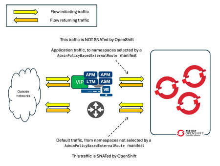
Controlling the egress traffic in OpenShift allows to use the BIG-IP for several use cases: Keeping the source IP of the ingress clients Providing highly scalable SNAT for egress flows Providing security functionalities for egress flows1.3KViews1like2CommentsDeploying F5 Distributed Cloud Customer Edge in Red Hat OpenShift Virtualization
Introduction Red Hat OpenShift Virtualization is a feature that brings virtual machine (VM) workloads into the Kubernetes platform, allowing them to run alongside containerized applications in a seamless, unified environment. Built on the open-source KubeVirt project, OpenShift Virtualization enables organizations to manage VMs using the same tools and workflows they use for containers. Why OpenShift Virtualization? Organizations today face critical needs such as: Rapid Migration: "I want to migrate ASAP" from traditional virtualization platforms to more modern solutions. Infrastructure Modernization: Transitioning legacy VM environments to leverage the benefits of hybrid and cloud-native architectures. Unified Management: Running VMs alongside containerized applications to simplify operations and enhance resource utilization. OpenShift Virtualization addresses these challenges by consolidating legacy and cloud-native workloads onto a single platform. This consolidation simplifies management, enhances operational efficiency, and facilitates infrastructure modernization without disrupting existing services. Integrating F5 Distributed Cloud Customer Edge (XC CE) into OpenShift Virtualization further enhances this environment by providing advanced networking and security capabilities. This combination offers several benefits: Multi-Tenancy: Deploy multiple CE VMs, each dedicated to a specific tenant, enabling isolation and customization for different teams or departments within a secure, multi-tenant environment. Load Balancing: Efficiently manage and distribute application traffic to optimize performance and resource utilization. Enhanced Security: Implement advanced threat protection at the edge to strengthen your security posture against emerging threats. Microservices Management: Seamlessly integrate and manage microservices, enhancing agility and scalability. This guide provides a step-by-step approach to deploying XC CE within OpenShift Virtualization, detailing the technical considerations and configurations required. Technical Overview Deploying XC CE within OpenShift Virtualization involves several key technical steps: Preparation Cluster Setup: Ensure an operational OpenShift cluster with OpenShift Virtualization installed. Access Rights: Confirm administrative permissions to configure compute and network settings. F5 XC Account: Obtain access to generate node tokens and download the XC CE images. Resource Optimization: Enable CPU Manager: Configure the CPU Manager to allocate CPU resources effectively. Configure Topology Manager: Set the policy to single-numa-node for optimal NUMA performance. Network Configuration: Open vSwitch (OVS) Bridges: Set up OVS bridges on worker nodes to handle networking for the virtual machines. NetworkAttachmentDefinitions (NADs): Use Multus CNI to define how virtual machines attach to multiple networks, supporting both external and internal connectivity. Image Preparation: Obtain XC CE Image: Download the XC CE image in qcow2 format suitable for KubeVirt. Generate Node Token: Create a one-time node token from the F5 Distributed Cloud Console for node registration. User Data Configuration: Prepare cloud-init user data with the node token and network settings to automate the VM initialization process. Deployment: Create DataVolumes: Import the XC CE image into the cluster using the Containerized Data Importer (CDI). Deploy VirtualMachine Resources: Apply manifests to deploy XC CE instances in OpenShift. Network Configuration Setting up the network involves creating Open vSwitch (OVS) bridges and defining NetworkAttachmentDefinitions (NADs) to enable multiple network interfaces for the virtual machines. Open vSwitch (OVS) Bridges Create a NodeNetworkConfigurationPolicy to define OVS bridges on all worker nodes: apiVersion: nmstate.io/v1 kind: NodeNetworkConfigurationPolicy metadata: name: ovs-vms spec: nodeSelector: node-role.kubernetes.io/worker: '' desiredState: interfaces: - name: ovs-vms type: ovs-bridge state: up bridge: allow-extra-patch-ports: true options: stp: true port: - name: eno1 ovn: bridge-mappings: - localnet: ce2-slo bridge: ovs-vms state: present Replace eno1 with the appropriate physical network interface on your nodes. This policy sets up an OVS bridge named ovs-vms connected to the physical interface. NetworkAttachmentDefinitions (NADs) Define NADs using Multus CNI to attach networks to the virtual machines. External Network (ce2-slo): External Network (ce2-slo): Connects VMs to the physical network with a specific VLAN ID. This setup allows the VMs to communicate with external systems, services, or networks, which is essential for applications that require access to resources outside the cluster or need to expose services to external users. apiVersion: k8s.cni.cncf.io/v1 kind: NetworkAttachmentDefinition metadata: name: ce2-slo namespace: f5-ce spec: config: | { "cniVersion": "0.4.0", "name": "ce2-slo", "type": "ovn-k8s-cni-overlay", "topology": "localnet", "netAttachDefName": "f5-ce/ce2-slo", "mtu": 1500, "vlanID": 3052, "ipam": {} } Internal Network (ce2-sli): Internal Network (ce2-sli): Provides an isolated Layer 2 network for internal communication. By setting the topology to "layer2", this network operates as an internal overlay network that is not directly connected to the physical network infrastructure. The mtu is set to 1400 bytes to accommodate any overhead introduced by encapsulation protocols used in the internal network overlay. apiVersion: k8s.cni.cncf.io/v1 kind: NetworkAttachmentDefinition metadata: name: ce2-sli namespace: f5-ce spec: config: | { "cniVersion": "0.4.0", "name": "ce2-sli", "type": "ovn-k8s-cni-overlay", "topology": "layer2", "netAttachDefName": "f5-ce/ce2-sli", "mtu": 1400, "ipam": {} } VirtualMachine Configuration Configuring the virtual machine involves preparing the image, creating cloud-init user data, and defining the VirtualMachine resource. Image Preparation Obtain XC CE Image: Download the qcow2 image from the F5 Distributed Cloud Console. Generate Node Token: Acquire a one-time node token for node registration. Cloud-Init User Data Create a user-data configuration containing the node token and network settings: #cloud-config write_files: - path: /etc/vpm/user_data content: | token: <your-node-token> slo_ip: <IP>/<prefix> slo_gateway: <Gateway IP> slo_dns: <DNS IP> owner: root permissions: '0644' Replace placeholders with actual network configurations. This file automates the VM's initial setup and registration. VirtualMachine Resource Definition Define the VirtualMachine resource, specifying CPU, memory, disks, network interfaces, and cloud-init configurations. Resources: Allocate sufficient CPU and memory. Disks: Reference the DataVolume containing the XC CE image. Interfaces: Attach NADs for network connectivity. Cloud-Init: Embed the user data for automatic configuration. Conclusion Deploying F5 Distributed Cloud CE in OpenShift Virtualization enables organizations to leverage advanced networking and security features within their existing Kubernetes infrastructure. This integration facilitates a more secure, efficient, and scalable environment for modern applications. For detailed deployment instructions and configuration examples, please refer to the attached PDF guide. Related Articles: BIG-IP VE in Red Hat OpenShift Virtualization VMware to Red Hat OpenShift Virtualization Migration OpenShift Virtualization1.7KViews2likes2Comments
feature request: container egress service
After installing cis in a test environment and getting ready to install in a new production environment I wonder if there also will be a container egress service (CES)? It is very easy to set a gateway for selected namespaces with AdminPolicyBasedExternalRoute in Openshift. See, F5 BIG-IP deployment with Red Hat OpenShift - keeping client IP addresses and egress flows | DevCentral The solution above does not scale well if multiple namespace-egress IP address mappings are desired. A nice solution would be a CES that watches the creating and deletion of pods in selected namespaces. Then it can manage address lists with the pods ip addresses in the F5 ltm. Forwarding ip virtual services will use these address lists to match pod ip addresses to an egress ip defined in a snat pool. Also the creation and deletion of forwarding ip virtual servers and address lists could be managed with a "CES". A possible issue is that a container in a pod can start network connections before the forwarding IP virtual server accepts the new pod IP address. But this can easily be solved with adding an initcontainer in the pod that tests the network connectivity. This would be a good alternative for Openshift egress IPs or Istio gateways. Reason to want this, is to offer applications on Openshift an own egress IP address and stop using the node IP address for external network connections of the pods.267Views0likes3Comments
Health Monitor unable to connect to OpenShift Router
Hi, We have F5 VS routing traffic to a service behind OpenShift Router ( We are not using F55 CIS ). The OpenShift Route is configured as TLS Passthrough. I want to re-encrypt TLS at F5. In case of TLS Passthrough configuration OpenShift Router determines the route based on TLS Client Hello hostname. So I have OPS Route with host name “my-tls-passthrough-service.com” and I have F5 VS with hostname “my-f5vs.com” and a pool with single member pointing to OPS Router IP and port 443 . I have configured Client and Server SSL profiles. Also, in server SSL profile I have set “Server Name” attribute to “my-tls-passthrough-service.com” . Everything works as expected – the request reaches the service through F5 . The problem I have is when I configure Health Monitor. The generic HTTPS monitor doesn’t help as it checks the status of OPS Router , not the service behind it. But when I add ServerSSL profile to Health check monitor I get pool member marked down and message in local traffic log “Unable to connect “ Can you please help - without health monitor the set up is useless665Views0likes4Commentsha cis multi cluster Openshift route creation
I like to verify that when creating a route on an Openshift multicluster HA cis environment, the endpoints of a service on the secondary cluster are added to the poolmembers automatically. First I had the annotation below add: virtual-server.f5.com/multiClusterServices: | [ { "clusterName": "openshift-engineering-02", "service": "tea-svc", "namespace": "cafe", "servicePort": 8080, "weight": 100 } ] Creating routes without this annotation still adds the pods of the service with the same name and in the same namespace on the secondary cluster I saw. Is this annotation not required for a HA cis multi cluster application? Does HA CIS always add the pods of the secondary cluster as poolmembers if they belong to the same service and namespace as on the primary cluster? And the same if the secondary CIS becomes the active CIS? What about services on other external clusters? Is the annotation for virtual-server.f5.com/multiClusterServices only required if the service or namespace do not match with the names in the route manifest?Solved335Views0likes2Commentsopenshift multi cluster CIS HA
I encounter a weird issue configuring a high available CIS 2.19 on Openshift 4.16. The primary cis hangs in a loop, printing: [WARNING] AutoMonitor value is not defined or not supported. Defaulting to none If I switch off the primary and start the secondary, the secondary works as should and creates the objects on the F5 big ip ve. For the routes defined on the secondary cluster. Attached are the deployment and configmap yamls. I could not find anything about the AutoMonitor, so I have no idea what this is. If I configure the primary cluster as a standalone, multi cluster works fine.Solved935Views0likes7Comments