networking
76 TopicsIPv8 Would Fix My Routing Tables. It Will Never Ship.
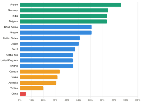
Anyone who worked on a service provider backbone in the late 90s or early 2000s remembers the squeeze. Cisco 7500s and early GSRs came with RAM budgets that looked generous at install and felt terrifying three years later, and the global BGP table kept growing faster than the hardware refresh cycle. Providers started summarizing aggressively, pushing back on customers who wanted to advertise /24s for traffic engineering, and progressively raising the minimum prefix length they’d accept at the edge. It was a real problem on both sides of every BGP session, and the fix was always the same conversation: “we’d love to carry all your cute disparate /25 CIDR blocks, but my RIBs are a little sore.” Twenty-five years later, the table is pushing toward a million prefixes. The hardware got bigger, and we quietly learned to live with a routing system whose growth has no architectural ceiling. So when I read this IPv8 draft and got to the part where the /16 minimum injectable prefix rule effectively caps the global table on the order of one entry per originating ASN, dropping us from ~900K prefixes to something closer to ~150–200K in steady state, I performed Balki’s dance of joy in my head (look it up, youngins!) and was ready to sign up on the spot. A bounded global routing table, WHOIS8 validation that meaningfully raises the bar on prefix hijacking, and a Cost Factor metric that actually accumulates end-to-end across AS boundaries instead of stopping at the edge. That’s three things the younger me wanted twenty years ago, bundled into one draft. Of note: this is an individual -00 Internet-Draft with no working-group adoption or visible industry backing yet. Plenty of RFCs started this way, but it's a design document at this stage, not a standards-track specification. But it’s not all puppies and rainbows. And the reason why gets to something more important: IPv6 didn’t struggle because it solved the wrong problem. It struggled because it solved only one problem in a system where operators needed several to be solved concurrently. Before I dig into why that matters for IPv8, let’s take a step back and consider the history of IP in general, because the reasons a proposal like this is hard to ship are the same reasons IPv6 is still stuck at half the internet three decades in. IPv4 has been carrying the internet since 1981, and its 32-bit address space, roughly 4.3 billion addresses, was declared exhausted at the IANA level in 2011. IPv6 was ratified as the official successor back in 1998 with a 128-bit address space, and despite nearly three decades of standards work, deployment campaigns, and World IPv6 Day t-shirts (who doesn’t love a good #nerd shirt?), it still carries a minority of overall traffic, even if the telecom percentage is now more than half. That’s the backdrop against which IPv8 is proposed. IPv8 is a proposed 64-bit successor to IPv4 that pairs an expanded address space with a unified management architecture. Addresses take the form r.r.r.r.n.n.n.n, where the first 32 bits encode an ASN and the last 32 are an IPv4-semantic host address. When r.r.r.r = 0.0.0.0, the address is IPv4, which the draft leans on to argue IPv4 is a proper subset of IPv8 and no flag day or dual-stack phase is needed. Beyond addressing, the draft specifies a “Zone Server” that collapses DHCP, DNS, NTP, OAuth2 auth, telemetry, route validation, ACLs, and IPv4↔IPv8 translation onto one platform. It also introduces an end-to-end Cost Factor routing metric, the /16 minimum prefix rule mentioned above, and mandatory egress validation that drops any packet without a matching DNS lookup and WHOIS8-registered route. How IPv8 Differs From IPv6 IPv6 was scoped narrowly: solve address exhaustion. It went to 128 bits, modernized some header mechanics, and left DHCP, DNS, auth, telemetry, and routing security to evolve on their own, which, thirty years later, they mostly still haven’t in any coordinated way. Transition assumed dual-stack everywhere until IPv4 could eventually be retired. Eventually is doing some heavy lifting in that sentence. IPv8's authors argue exhaustion is only one of three structural IPv4 failures, the others being management, fragmentation and unbounded, unvalidated BGP, and try to solve all three at once while rejecting dual-stack outright. Addressing, routing, identity, policy, and telemetry are treated as one system. That’s either exactly what the industry needed, or exactly why it won’t ship. Why IPv6 Adoption Stalled We’ll get into the reasons below, but it’s worth looking at where things actually stand. The headline numbers people quote for IPv6 come from Google, APNIC, and Cloudflare, all of which measure eyeball-to-content traffic, users reaching public services. Here’s how that breaks down by country as of early 2026 (Is that FRANCE leading the way?!?): Dual-stack did most of the damage. Running both protocols in parallel roughly doubled the config, monitoring, firewall, and troubleshooting surface area with nothing new to show for it operationally. Cost was immediate; benefit was deferred to a day that kept sliding to the right. Every network engineer who has debugged a dual-stack MTU issue at 2am has opinions about this. Carrier-grade NAT finished the job. Once ISPs could stretch IPv4 with CGNAT, the exhaustion crisis stopped being acute and quietly became someone else’s problem, specifically the problem of whoever was trying to run a peer-to-peer protocol through three layers of translation. Add a non-backward-compatible header and 128-bit colon-hex notation that fights operator muscle memory, and the business case never really came together. We’ve spent three decades turning the “IPv6 is coming” war cry into the networking equivalent of fusion power. The Enterprise Internal-Network Blind Spot The country-level numbers above tell you what mobile carriers and residential ISPs have shipped. They don’t tell you anything about the LAN side of the corporate firewall, which is a completely different story. Internal enterprise IPv6 adoption is sitting somewhere between 20% and 30% and has barely moved in a decade, a gap the headline statistics quietly gloss over. A few data points worth knowing: RFC 9386 (IPv6 Deployment Status), the closest thing to an official IETF status report, surveyed European service providers in 2020 and found the enterprise segment lagging mobile and fixed broadband even when measured from the provider’s perspective. Internal deployment numbers were mostly not collected because they were understood to be negligible. HexaBuild's IPv6 Adoption Reports from 2018 and 2020 explicitly call out that “many commercial enterprises still lack IPv6 connectivity at their Internet perimeters and don’t have any IPv6 network connectivity in their internal networks.” Follow-on coverage hasn’t meaningfully changed that framing. OMB Memorandum M-21-07 required US federal agencies to hit 80% IPv6-only on internal assets by September 30, 2025. As of October 2025, no federal agency has publicly announced reaching that threshold. This is a mandate with five years of runway, presidential-memo weight, and FAR procurement backing, and it still missed its own deadline across essentially every agency. The reasons internal adoption is stuck are painfully mundane, and every network engineer reading this will recognize them: RFC 1918 solved the address problem thirty years ago. 10.0.0.0/8 gives you 16 million addresses. Unless you’re a hyperscaler or you’ve acquired your way into overlapping subnet hell, that’s functionally infinite. It’s hard to sell a renumbering project to a CFO when the existing scheme has never once failed to have enough addresses. Every piece of tooling assumes IPv4. Firewalls, load balancers, IPAM, NetFlow collectors, ACL generators, SIEM parsers, monitoring dashboards, runbooks, change management templates, and the regex in that one critical Perl script from 2008, all of it was written for dotted-quad. Dual-stack means maintaining two of everything with no operational payoff. Troubleshooting costs roughly double that. Anyone who has tried to correlate a dual-stack flow across a load balancer, a WAF, and three microservices knows exactly why executives didn’t approve the project. The failure modes aren’t symmetric. An IPv6-only path can break in ways that leave the IPv4 path working, which means “it works on my machine” becomes “it works on my protocol family.” Security teams often see IPv6 as a new attack surface rather than a modernized infrastructure. Auto-configuration and neighbor discovery behave differently enough from ARP that existing segmentation, spoofing, and rogue-device playbooks need to be rewritten. For a team already underwater on IPv4 incidents, opting into a second set of attack patterns is a hard sell. There’s no customer-visible benefit. The user doesn’t care what protocol their apps run on internally. The CIO/CISO might (ok, for sure) have an opinion, but the CFO definitely doesn’t. This is actually a stronger argument for the IPv8 approach than the draft itself makes. The reason IPv6 bounced off the enterprise LAN is that it offered zero operational improvement over what RFC 1918 and NAT were already providing. IPv8’s pitch, that IPv4 is a proper subset, that internal networks keep their existing addressing, and that the management story is the value proposition rather than the address space, is at least aimed at the right problem. Pros & Cons No proposal this ambitious gets everything right or everything wrong, and IPv8 is no exception. A few things it nails, a few things it doesn’t, and one quiet standout worth calling out even if the rest of the draft never ships. Pros Backward compatibility is the one thing this gets right that IPv6 got wrong. Encoding IPv4 as IPv8 with a zero ASN prefix means existing applications, RFC 1918 networks, and CGNAT deployments don’t need to change to keep working. If that claim holds up in implementation, it sidesteps the single biggest political failure of the IPv6 transition, the one where you had to convince every stakeholder in the chain to move at the same time for anyone to benefit. The management-fragmentation critique is strong, and the answer makes a lot of sense. Networking from disparate angles doesn’t exactly evoke a thoughtful design pattern, but feels more like a whack-a-mole approach. DHCP, DNS, syslog, SNMP, and auth really were specified independently over four decades with no shared identity or telemetry model, and anyone who’s ever tried to correlate an incident across them knows the pain. A Zone Server with OAuth2/JWT as the common substrate is a reasonable swing at it, and it’s refreshing to see a proposal treat operations as a first-class concern instead of an exercise left to the reader. Cost Factor is the routing metric OSPF and EIGRP always wanted to be. CF accumulates seven signals: RTT, loss, congestion window state, session stability, link capacity, economic policy, and great-circle distance as a physics floor, end-to-end across AS boundaries, which is exactly where OSPF and EIGRP stop being useful. The geographic component is the clever bit: no path can measure faster than the speed of light over the great circle distance allows, so a path that appears better than physics permits is flagged as an anomaly instead of silently poisoning route selection. That’s a better hijack detector than most of what we have today, and it falls out of the metric for free. Honorable mention: bounded routing table. Already covered in the intro, but worth restating that the /16 minimum-prefix rule plus mandatory WHOIS8 validation is the structural fix for both unbounded RIB growth and prefix hijacking. If any single piece of this draft gets adopted à la carte, this is the one I’d bet on. Cons “No dual stack" understates the deployment reality. IPv4 packets transit an IPv8 router fine, but anything that actually uses the ASN prefix (new header fields, A8 records, AF_INET8 sockets, 8to4 tunneling, WHOIS8 egress validation) requires updated stacks, resolvers, middleboxes, firewalls, and applications. Backward-compatible is not the same as zero deployment cost, and the draft blurs the two in a way that will feel familiar to anyone who remembers the original “IPv6 is a drop-in replacement" sales pitch. The Zone Server is a massive trust and failure domain. This is the part that should make operators nervous. We've spent the last twenty years decomposing monoliths, breaking apart control planes, distributing systems, and reducing blast radius. The Zone Server pulls DHCP, DNS, auth, telemetry, validation, and policy back into a single logical system. Even with active/active HA, it’s a high-value target, it expands the trust boundary significantly, and a bad day becomes a very bad day. We’ve seen this pattern before in other control-plane centralizations. It works great…until it doesn’t. The scope is probably fatal to adoption. Ten companion drafts covering a new IP version, five routing protocols, a new exchange-point architecture, a zone-server platform, support protocols, a MIB, WiFi8, and mandatory NIC certification with hardware-enforced rate limits is the opposite of how the IETF actually ships things. The institutional motto is “rough consensus and running code”, not “ten coordinated drafts and a reference architecture.” I love the crazy ambition, but narrow, incrementally deployable specs get adopted. Monolithic suites rarely do, just ask OSI. The Real Roadblock: Incentives IPv8 won’t fail because it’s too ambitious. It will fail because no one with budget authority is experiencing enough pain to justify replacing the system. For it to succeed, the RIRs would need to stand up WHOIS8 as a high-availability egress-gating service, and RPKI, a much narrower version of the same idea, is still partially deployed fifteen years in (don’t get Chase started). At least one major vendor (Cisco, Juniper, Arista, Nokia, or the merchant-silicon ecosystem) would need to publicly commit to shipping IPv8 forwarding, certified NIC firmware, and Zone Server reference code, while somehow reconciling the “just a software update” framing with the mandatory NIC certification and hardware rollback prevention the draft also requires. And the hyperscalers, who have already solved VPC overlap and multi-cloud routing on their own terms, would need a reason to adopt a standard that constrains their existing architecture. Meanwhile, CGNAT works well enough. Hyperscalers have already built their own solutions. And operational pain sits with engineers, not executives, which is the same incentive gap that killed IPv6 momentum. The draft answer, that Cost Factor will naturally incentivize IPv4 transit ASNs to upgrade because 8to4 paths measure slower, is clever but requires enough IPv8 traffic to exist for the signal to register, which is the same chicken-and-egg problem IPv6 has been losing for thirty years. There’s a faint echo here of other efforts like segment routing and SD-WAN where pieces of this vision are already being adopted, just not as a single unified system. That’s probably the shape of whatever actually ships. Bottom Line The diagnosis is on point. Management fragmentation, unbounded BGP, unauthenticated routing, and CGNAT's drag on peer-to-peer protocols are real problems that IPv6 didn’t address and that the industry has mostly absorbed as permanent friction in their engineering and operational playbooks. IPv6 addresses one of them. IPv8 tries to address all of them at once, and that’s both its strength and the reason it probably won’t ship. If anything from this proposal survives, it will likely be the smaller pieces (stronger route validation, better routing metrics, more cohesive management models) adopted incrementally rather than as a full replacement. Which is a bit of a shame, because a bounded routing table alone would have solved one of the hardest conversations of my early career. IPv8 is what the internet might look like if it were designed today. Unfortunately, the internet we have is the one that has to adopt it. What do you think? Come at me and my IPv8 hot takes!2.4KViews2likes0Comments
Issue with 2 parallel F5 clusters
Hello everybody and first of all thank you for taking the time to read my issue! The issue that I have is in regards to a migration We have a productive F5 BigIP cluster (Active/Standby), let's call this "Old F5", which has a lot of Virtual Servers in partitions, with specific pools and monitors for each application/service This device also has 2 Vlans, internal (vlan11) and external (vlan10), and 2 interfaces in an LACP that it's tagged on both Vlans, and it's connected to the same one leg to a Cisco APIC It has 2 Self IP addresses (one for each Vlan): 10.10.10.1-Vlan "external" 10.20.20.1-Vlan "internal" (numbers are just for example) It also has 4 Floating IP address (2 for each Vlan) with 2 traffic groups: 10.10.10.2-Vlan external traffic group 1 10.10.10.3-Vlan external traffic group 2 10.20.20.2-Vlan internal traffic group 1 10.20.20.3-Vlan internal traffic group 2 This device (cluster) has to be replaced by another F5 BigIP cluster (let's call this new F5), this device is an identical copy to the old F5 (the config was took from the old one and imported to the new one), meaning same Vlans, monitors, pools, VServers IP addresses etc At the moment this one has the 2 interfaces disabled and a blackhole default reject route set up in order to not interfere with the old F5 which is the productive one. The ideea is to configure the new F5 device with IP addresses from the same subnet (for example 10.10.10.5), and disable all the Virtual Servers so it doesn't handle traffic (the nodes, monitors, pools stay up on both devices), and have the 2 F5 devices, old and new, running in parallel and then move the Virtual servers one by one by just disabling the VS on the old F5 and enable it on the new F5. At this point we also remove the blackhole route, configure the correct default static route (the same which is on the old F5), and enable the interfaces This sounded and looked good, on the new F5 the nodes, pools are green and the Virtual servers are disabled as expected. On the old productive F5 everything is up and green BUT if I try to reach one of the Virtual servers, either by the Virtual IP address or hostname the attempt just times out without any response (if I try to telnet to the VS on port 443 it connects meaning that the old F5 accepts the traffic) I tried to disable on the new F5 also the nodes but still the same behaviour, the only to get it back to work is to disable the interfaces on the new F5 and add the default reject blackhole route. This is not how I imagined it to work, in my mind I was expecting that the old F5 will work as normal, and the new F5 device will see the nodes and pools up (confirming good communication) but don't handle any traffic regarding the Virtual servers because they are disabled. Does anyone have any idea what is causing this issue, why when both F5 devices are up in parallel, the connection to the Virtual server through the old productive F5 times out while that F5 sees both the pools and Virtual servers as up and running. Thank you in advance!317Views0likes3Comments
Need help to understand operation between RE and CE ?
Hi all, We have installed CE site in our network and this site has established IPSEC tunnels with RE nodes. The on-prem DC site has workloads (e.g actual web application servers that are serving the client requests). I have citrix netscaler background and the Citrix Netscalers ADCs are configured with VIPs which are the frontend for the client requests coming from outside (internet), when the request land on VIPs, it goes through both source NAT and destination NAT, its source address is changed to private address according to the service where the actual application servers are configured and then sent to the actual application server after changing the destination to IP address of the server. In XC, the request will land to the cloud first because the public IP, which is assigned to us will lead the request to RE. I have few questions regarding the events that will happen from here after Will there going to be any SNAT on the request or will it send it as it is to the site? And if there is SNAT then what IP address will it be ? and will it be done by the RE or on-prem CE There has to be destination NAT. Will this destination NAT is going to be performed by the XC cloud or the request will be sent to the site and site will do the destination NAT ? When the request will land the CE it will be landed in VN local outside so this means that we have to configure the network connector between the VN Local outside and the VN in which the actual workloads are configured, what type of that VN would be ? When the request will be responded by the application server in local on-prem the site the request has to go out to the XC cloud first, it will be routed via IPSEC tunnel so this means that we have to install the network connector between the Virtual network where the workloads are present and site local outside, do we have to install the default route in application VN ? Is there any document, post or article that actually help me to understand the procedure (frankly I read a lot of F5 documents but couldn’t able to find the answers1.2KViews0likes10Comments
Different Route's for Different Subnets on the same partition
Hi Guys, When someone set up our F5 they created multiple partitions for different segments. We are trying to reconfigure the F5 to all everything running from the common partition. We currently have our public wifi authentication happening via the F5 on a subnet REDACTED That is working fine because we have a route with REDACTED to the correct gateway. I also want to create VS with the subnet REDACTED Now we have the self ip's in place, and the Vlans are in the same route domain (0). The issue I am facing is I can get to the back end of the VS, however if I remove the default route for the public wifi and add the gateway for the REDACTED network I can then access that but not the public Wi-Fi. Can anyone help or provide a suggestion as to how I can get both subnets working on the same partition?974Views0likes7Comments
Back to Basics: The Many Modes of Proxies
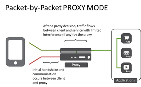
The simplicity of the term "proxy" belies the complex topological options available. Understanding the different deployment options will enable your proxy deployment to fit your environment and, more importantly, your applications. It seems so simple in theory. A proxy is a well-understood concept that is not peculiar to networking. Indeed, some folks vote by proxy, they speak by proxy (translators), and even on occasion, marry by proxy. A proxy, regardless of its purpose, sits between two entities and performs a service. In network architectures the most common use of a proxy is to provide load balancing services to enable scale, reliability and even performance for applications. Proxies can log data exchanges, act as a gatekeeper (authentication and authorization), scan inbound and outbound traffic for malicious content and more. Proxies are a key strategic point of control in the data center because they are typically deployed as the go-between for end-users and applications. These go-between services are often referred to as virtual services, and for purposes of this blog that's what we'll call them. It's an important distinction because a single proxy can actually act in multiple modes on a per-virtual service basis. That's all pretty standard stuff. What's not simple is when you start considering how you want your proxy to act. Should it be a full proxy? A half proxy? Should it route or forward? There are multiple options for these components and each has its pros and cons. Understanding each proxy "mode" is an important step toward architecting a suitable solution for your environment as the mode determines the behavior of traffic as it traverses the proxy. Standard Virtual Service (Full Application Proxy) The standard virtual service provided by a full proxy fully terminates the transport layer connections (typically TCP) and establishes completely separate transport layer connections to the applications. This enables the proxy to intercept, inspect and ultimate interact with the data (traffic) as its flowing through the system. Any time you need to inspect payloads (JSON, HTML, XML, etc...) or steer requests based on HTTP headers (URI, cookies, custom variables) on an ongoing basis you'll need a virtual service in full proxy mode. A full proxy is able to perform application layer services. That is, it can act on protocol and data transported via an application protocol, such as HTTP. Performance Layer 4 Service (Packet by Packet Proxy) Before application layer proxy capabilities came into being, the primary model for proxies (and load balancers) was layer 4 virtual services. In this mode, a proxy can make decisions and interact with packets up to layer 4 - the transport layer. For web traffic this almost always equates to TCP. This is the highest layer of the network stack at which SDN architectures based on OpenFlow are able to operate. Today this is often referred to as flow-based processing, as TCP connections are generally considered flows for purposes of configuring network-based services. In this mode, a proxy processes each packet and maps it to a connection (flow) context. This type of virtual service is used for traffic that requires simple load balancing, policy network routing or high-availability at the transport layer. Many proxies deployed on purpose-built hardware take advantage of FPGAs that make this type of virtual service execute at wire speed. A packet-by-packet proxy is able to make decisions based on information related to layer 4 and below. It cannot interact with application-layer data. The connection between the client and the server is actually "stitched" together in this mode, with the proxy primarily acting as a forwarding component after the initial handshake is completed rather than as an endpoint or originating source as is the case with a full proxy. IP Forwarding Virtual Service (Router) For simple packet forwarding where the destination is based not on a pooled resource but simply on a routing table, an IP forwarding virtual service turns your proxy into a packet layer forwarder. A IP forwarding virtual server can be provisioned to rewrite the source IP address as the traffic traverses the service. This is done to force data to return through the proxy and is referred to as SNATing traffic. It uses transport layer (usually TCP) port multiplexing to accomplish stateful address translation. The address it chooses can be load balanced from a pool of addresses (a SNAT pool) or you can use an automatic SNAT capability. Layer 2 Forwarding Virtual Service (Bridge) For situations where a proxy should be used to bridge two different Ethernet collision domains, a layer 2 forwarding virtual service an be used. It can be provisioned to be an opaque, semi-opaque, or transparent bridge. Bridging two Ethernet domains is like an old timey water brigade. One guy fills a bucket of water (the client) and hands it to the next guy (the proxy) who hands it to the destination (the server/service) where it's thrown on the fire. The guy in the middle (the proxy) just bridges the gap (you're thinking what I'm thinking - that's where the term came from, right?) between the two Ethernet domains (networks).2.8KViews0likes3Comments
Bidirectional Forwarding Detection (BFD) Protocol Cheat Sheet
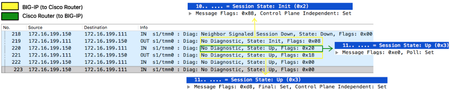
Definition This is a protocol initially described in RFC5880 and IPv4/IPv6 specifics in RFC5881. I would say this is an aggressive 'hello-like' protocol with shorter timers but very lightweight on the wire and requiring very little processing as it is designed to be implemented in forwarding plane (although RFC does not forbid it to be implemented in control plane). It also contains a feature called Echo that further leaves cpu processing cycle to roughly ZERO which literally just 'loops' BFD control packets sent from peer back to them without even 'touching' (processing) it. BFD helps routing protocol detects peers failure at sub-second level and BIG-IP supports it on all its routing protocols. On BIG-IP it is control-plane independent as TMM that takes care of BFD sending/receiving unicast probes (yes, no multicast!) and BIG-IP's Advanced Routing Module® being responsible only for its configuration (of course!) and to receive state information from TMM that is displayed in show commands. BIG-IP's control plane daemon communicates with TMM is oamd. This daemon starts when BFD is enabled in the route domain like any other routing protocol. BFD Handshake Explained 218: BFD was configured on Cisco Router but not on BIG-IP so neighbour signals BIG-IP sessionstate is Down and no flags 219: I had just enabled BFD on BIG-IP, session state is now Init and only Control Plane Independent flag set¹ 220: Poll flag is set to validate initial bidirectional connectivity (expecting Final flag set in response) 221: BIG-IP sets Final flag and handshake is complete² ¹Control Plane Independent flag is set because BFD is not actively performed by BIG-IP's control plane. BIG-IP's BFD control plane daemon (oamd) just signals TMM what BFD sessions are required and TMM takes care of sending/receiving of all BFD control traffic and informs session state back to Advanced Routing Module's daemon. ²Packets 222-223 are just to show that after handshake is finished all flags are cleared unless there is another event that triggers them. Packet 218 is how Cisco Router sees BIG-IP when BFD is not enabled. Control Plane Independent flag on BIG-IP remains though for the reasons already explained above. Protocol fields Diagnostic codes 0 (No Diagnostic): Typically seen when BFD session is UP and there are no errors. 1 (Control Detection Time Expired): BFD Detect Timer expired and session was marked down. 2 (Echo Function Failed): BFD Echo packet loop verification failed, session is marked down and this is the diagnostic code number. 3 (Neighbor Signaled Session Down): If either neighbour advertised state or our local state is down you will see this diagnostic code 4 (Forwarding Planet Reset): When forwarding-plane (TMM) is reset and peer should not rely on BFD so session is marked down. 5 (Path Down): On demand mode external application can signal BFD that path is down so we can set session down using this code 6 Concatenated Path Down): 7 (Administratively Down): Session is marked down by an administrator 8 (Reverse Concatenated Path Down): 9-31: Reserved for future use BFD verification 'show' commands ³Type IP address to see specific session Modes Asynchronous (default): hello-like mode where BIG-IP periodically sends (and receives) BFD control packets and if control detection timer expires, session is marked as down. It uses UDP port 3784. Demand: BFD handshake is completed but no periodic BFD control packets are exchanged as this mode assumes system has its own way of verifying connectivity with peer and may trigger BFD verification on demand, i.e. when it needs to use it according to its implementation. BIG-IP currently does not support this mode. Asynchronous + Echo Function: When enabled, TMM literally loops BFD echo-specific control packets on UDP port 3785 sent from peers back to them without processing it as it wasn't enough that this protocol is already lightweight. In this mode, a less aggressive timer (> 1 second) should be used for regular BFD control packets over port 3784 and more aggressive timer is used by echo function. BIG-IP currently does not support this mode. Header Fields Protocol Version: BFD version used. Latest one is v1 (RFC5880) Diagnostic Code: BFD error code for diagnostics purpose. Session State: How transmitting system sees the session state which can be AdminDown, Down, Init or Up. Message Flags: Additional session configuration or functionality (e.g. flag that says authentication is enabled) Detect Time Multiplier: Informs remote peer BFD session is supposed to be marked down if Desired Min TX Interval multiplied by this value is reached Message Length (bytes): Length of BFD Control packet My Discriminator: For each BFD session each peer will use a unique discriminator to differentiate multiple session. Your Discriminator: When BIG-IP receives BFD control message back from its peer we add peer's My Discriminator to Your Discriminator in our header. Desired Min TX Interval (microseconds): Fastest we can send BFD control packets to remote peer (no less than configured value here) Required Min RX Interval (microseconds): Fastest we can receive BFD control packets from remote peer (no less than configured value here) Required Min Echo Interval (microseconds): Fastest we can loop BFD echo packets back to remote system (0 means Echo function is disabled) Session State AdminDown: Administratively forced down by command Down: Either control detection time expired in an already established BFD session or it never came up. If probing time (min_tx) is set to 100ms for example, and multiplier is 3 then no response after 300ms makes system go down. Init: Signals a desire to bring session up in the beginning of BFD handshake. Up: Indicates session is Up Message Flags Poll: Pool flag is just a 'ping' that requires peer box to respond with Final flag. In BFD handshake as well as in Demand mode pool message is a request to validate bidirectional connectivity. Final: Sent in response to packet with Poll bit set Control Plane Independent: Set if BFD can continue to function if control plane is disrupted¹ Authentication Present: Only set if authentication is being used Demand: If set, it is implied that periodic BFD control packets are no longer sent and another mechanism (on demand) is used instead. Multipoint: Reserved for future use of point-to-multipoint extension. Should be 0 on both sides. ¹ This is the case for BIG-IP as BFD is implemented in forwarding plane (TMM) BFD Configuration Configure desired transmit and receive intervals as well as multiplier on BIG-IP. And Cisco Router: You will typically configure the above regardless of routing protocol used. BFD BGP Configuration And Cisco Router: BFD OSPFv2/v3 Configuration BFD ISIS Configuration BFD RIPv1/v2 Configuration BFD Static Configuration All interfaces no matter what: Specific interface only: Tie BFD configuration to static route:11KViews0likes7CommentsHTML5 Web Sockets Changes the Scalability Game
#HTML5 Web Sockets are poised to completely change scalability models … again. Using Web Sockets instead of XMLHTTPRequest and AJAX polling methods will dramatically reduce the number of connections required by servers and thus has a positive impact on performance. But that reliance on a single connection also changes the scalability game, at least in terms of architecture. Here comes the (computer) science… If you aren’t familiar with what is sure to be a disruptive web technology you should be. Web Sockets, while not broadly in use (it is only a specification, and a non-stable one at that) today is getting a lot of attention based on its core precepts and model. Web Sockets Defined in the Communications section of the HTML5 specification, HTML5 Web Sockets represents the next evolution of web communications—a full-duplex, bidirectional communications channel that operates through a single socket over the Web. HTML5 Web Sockets provides a true standard that you can use to build scalable, real-time web applications. In addition, since it provides a socket that is native to the browser, it eliminates many of the problems Comet solutions are prone to. Web Sockets removes the overhead and dramatically reduces complexity. - HTML5 Web Sockets: A Quantum Leap in Scalability for the Web So far, so good. The premise upon which the improvements in scalability coming from Web Sockets are based is the elimination of HTTP headers (reduces bandwidth dramatically) and session management overhead that can be incurred by the closing and opening of TCP connections. There’s only one connection required between the client and server over which much smaller data segments can be sent without necessarily requiring a request and a response pair. That communication pattern is definitely more scalable from a performance perspective, and also has a positive impact of reducing the number of connections per client required on the server. Similar techniques have long been used in application delivery (TCP multiplexing) to achieve the same results – a more scalable application. So far, so good. Where the scalability model ends up having a significant impact on infrastructure and architectures is the longevity of that single connection: Unlike regular HTTP traffic, which uses a request/response protocol, WebSocket connections can remain open for a long time. - How HTML5 Web Sockets Interact With Proxy Servers This single, persistent connection combined with a lot of, shall we say, interesting commentary on the interaction with intermediate proxies such as load balancers. But ignoring that for the nonce, let’s focus on the “remain open for a long time.” A given application instance has a limit on the number of concurrent connections it can theoretically and operationally manage before it reaches the threshold at which performance begins to dramatically degrade. That’s the price paid for TCP session management in general by every device and server that manages TCP-based connections. But Lori, you’re thinking, HTTP 1.1 connections are persistent, too. In fact, you don’t even have to tell an HTTP 1.1 server to keep-alive the connection! This really isn’t a big change. Whoa there hoss, yes it is. While you’d be right in that HTTP connections are also persistent, they generally have very short connection timeout settings. For example, the default connection timeout for Apache 2.0 is 15 seconds and for Apache 2.2 a mere 5 seconds. A well-tuned web server, in fact, will have thresholds that closely match the interaction patterns of the application it is hosting. This is because it’s a recognized truism that long and often idle connections tie up server processes or threads that negatively impact overall capacity and performance. Thus the introduction of connections that remain open for a long time changes the capacity of the server and introduces potential performance issues when that same server is also tasked with managing other short-lived, connection-oriented requests. Why this Changes the Game… One of the most common inhibitors of scale and high-performance for web applications today is the deployment of both near-real-time communication functions (AJAX) and traditional web content functions on the same server. That’s because web servers do not support a per-application HTTP profile. That is to say, the configuration for a web server is global; every communication exchange uses the same configuration values such as connection timeouts. That means configuring the web server for exchanges that would benefit from a longer time out end up with a lot of hanging connections doing absolutely nothing because they were used to grab standard dynamic or static content and then ignored. Conversely, configuring for quick bursts of requests necessarily sets timeout values too low for near or real-time exchanges and can cause performance issues as a client continually opens and re-opens connections. Remember, an idle connection is a drain on resources that directly impacts the performance and capacity of applications. So it’s a Very Bad Thing™. One of the solutions to this somewhat frustrating conundrum, made more feasible by the advent of cloud computing and virtualization, is to deploy specialized servers in a scalability domain-based architecture using infrastructure scalability patterns. Another approach to ensuring scalability is to offload responsibility for performance and connection management to an appropriately capable intermediary. Now, one would hope that a web server implementing support for both HTTP and Web Sockets would support separately configurable values for communication settings on at least the protocol level. Today there are very few web servers that support both HTTP and Web Sockets. It’s a nascent and still evolving standard so many of the servers are “pure” Web Sockets servers, many implemented in familiar scripting languages like PHP and Python. Which means two separate sets of servers that must be managed and scaled. Which should sound a lot like … specialized servers in a scalability domain-based architecture. The more things change, the more they stay the same. The second impact on scalability architectures centers on the premise that Web Sockets keep one connection open over which message bits can be exchanged. This ties up resources, but it also requires that clients maintain a connection to a specific server instance. This means infrastructure (like load balancers and web/application servers) will need to support persistence (not the same as persistent, you can read about the difference here if you’re so inclined). That’s because once connected to a Web Socket service the performance benefits are only realized if you stay connected to that same service. If you don’t and end up opening a second (or Heaven-forbid a third or more) connection, the first connection may remain open until it times out. Given that the premise of the Web Socket is to stay open – even through potentially longer idle intervals – it may remain open, with no client, until the configured time out. That means completely useless resources tied up by … nothing. Persistence-based load balancing is a common feature of next-generation load balancers (application delivery controllers) and even most cloud-based load balancing services. It is also commonly implemented in application server clustering offerings, where you’ll find it called server-affinity. It is worth noting that persistence-based load balancing is not without its own set of gotchas when it comes to performance and capacity. THE ANSWER: ARCHITECTURE The reason that these two ramifications of Web Sockets impacts the scalability game is it requires an broader architectural approach to scalability. It can’t necessarily be achieved simply by duplicating services and distributing the load across them. Persistence requires collaboration with the load distribution mechanism and there are protocol-based security constraints with respect to incorporating even intra-domain content in a single page/application. While these security constraints are addressable through configuration, the same caveats with regards to the lack of granularity in configuration at the infrastructure (web/application server) layer must be made. Careful consideration of what may be accidentally allowed and/or disallowed is necessary to prevent unintended consequences. And that’s not even starting to consider the potential use of Web Sockets as an attack vector, particularly in the realm of DDoS. The long-lived nature of a Web Socket connection is bound to be exploited at some point in the future, which will engender another round of evaluating how to best address application-layer DDoS attacks. A service-focused, distributed (and collaborative) approach to scalability is likely to garner the highest levels of success when employing Web Socket-based functionality within a broader web application, as opposed to the popular cookie-cutter cloning approach made exceedingly easy by virtualization. Infrastructure Scalability Pattern: Partition by Function or Type Infrastructure Scalability Pattern: Sharding Sessions Amazon Makes the Cloud Sticky Load Balancing Fu: Beware the Algorithm and Sticky Sessions Et Tu, Browser? Forget Hyper-Scale. Think Hyper-Local Scale. Infrastructure Scalability Pattern: Sharding Streams Infrastructure Architecture: Whitelisting with JSON and API Keys Does This Application Make My Browser Look Fat? HTTP Now Serving … Everything1.3KViews0likes5CommentsPersistent and Persistence, What's the Difference?
The English language is one of the most expressive, and confusing, in existence. Words can have different meaning based not only on context, but on placement within a given sentence. Add in the twists that come from technical jargon and suddenly you've got words meaning completely different things. This is evident in the use of persistent and persistence. While the conceptual basis of persistence and persistent are essentially the same, in reality they refer to two different technical concepts. Both persistent and persistence relate to the handling of connections. The former is often used as a general description of the behavior of HTTP and, necessarily, TCP connections, though it is also used in the context of database connections. The latter is most often related to TCP/HTTP connection handling but almost exclusively in the context of load-balancing. Persistent Persistent connections are connections that are kept open and reused. The most commonly implemented form of persistent connections are HTTP, with database connections a close second. Persistent HTTP connections were implemented as part of the HTTP 1.1 specification as a method of improving the efficiency Related Links HTTP 1.1 RFC Persistent Connection Behavior of Popular Browsers Persistent Database Connections Apache Keep-Alive Support Cookies, Sessions, and Persistence of HTTP in general. Before HTTP 1.1 a browser would generally open one connection per object on a page in order to retrieve all the appropriate resources. As the number of objects in a page grew, this became increasingly inefficient and significantly reduced the capacity of web servers while causing browsers to appear slow to retrieve data. HTTP 1.1 and the Keep-Alive header in HTTP 1.0 were aimed at improving the performance of HTTP by reusing TCP connections to retrieve objects. They made the connections persistent such that they could be reused to send multiple HTTP requests using the same TCP connection. Similarly, this notion was implemented by proxy-based load-balancers as a way to improve performance of web applications and increase capacity on web servers. Persistent connections between a load-balancer and web servers is usually referred to as TCP multiplexing. Just like browsers, the load-balancer opens a few TCP connections to the servers and then reuses them to send multiple HTTP requests. Persistent connections, both in browsers and load-balancers, have several advantages: Less network traffic due to less TCP setup/teardown. It requires no less than 7 exchanges of data to set up and tear down a TCP connection, thus each connection that can be reused reduces the number of exchanges required resulting in less traffic. Improved performance. Because subsequent requests do not need to setup and tear down a TCP connection, requests arrive faster and responses are returned quicker. TCP has built-in mechanisms, for example window sizing, to address network congestion. Persistent connections give TCP the time to adjust itself appropriately to current network conditions, thus improving overall performance. Non-persistent connections are not able to adjust because they are open and almost immediately closed. Less server overhead. Servers are able to increase the number of concurrent users served because each user requires fewer connections through which to complete requests. Persistence Persistence, on the other hand, is related to the ability of a load-balancer or other traffic management solution to maintain a virtual connection between a client and a specific server. Persistence is often referred to in the application delivery networking world as "stickiness" while in the web and application server demesne it is called "server affinity". Persistence ensures that once a client has made a connection to a specific server that subsequent requests are sent to the same server. This is very important to maintain state and session-specific information in some application architectures and for handling of SSL-enabled applications. Examples of Persistence Hash Load Balancing and Persistence LTM Source Address Persistence Enabling Session Persistence 20 Lines or Less #7: JSessionID Persistence When the first request is seen by the load-balancer it chooses a server. On subsequent requests the load-balancer will automatically choose the same server to ensure continuity of the application or, in the case of SSL, to avoid the compute intensive process of renegotiation. This persistence is often implemented using cookies but can be based on other identifying attributes such as IP address. Load-balancers that have evolved into application delivery controllers are capable of implementing persistence based on any piece of data in the application message (payload), headers, or at in the transport protocol (TCP) and network protocol (IP) layers. Some advantages of persistence are: Avoid renegotiation of SSL. By ensuring that SSL enabled connections are directed to the same server throughout a session, it is possible to avoid renegotiating the keys associated with the session, which is compute and resource intensive. This improves performance and reduces overhead on servers. No need to rewrite applications. Applications developed without load-balancing in mind may break when deployed in a load-balanced architecture because they depend on session data that is stored only on the original server on which the session was initiated. Load-balancers capable of session persistence ensure that those applications do not break by always directing requests to the same server, preserving the session data without requiring that applications be rewritten. Summize So persistent connections are connections that are kept open so they can be reused to send multiple requests, while persistence is the process of ensuring that connections and subsequent requests are sent to the same server through a load-balancer or other proxy device. Both are important facets of communication between clients, servers, and mediators like load-balancers, and increase the overall performance and efficiency of the infrastructure as well as improving the end-user experience.5.8KViews0likes2Comments
vCMP Host and Guest Communication
Hi All, I'm having some difficulty with some pre-testing that I'm doing for a vCMP Host - Guest design and hoping somebody here could steer me in the right direction. Basically, the deployment is very restrictive in terms of isolation so for each environment (UAT/PPD/PRD) we have presentation, abstraction and database networks. Due to the restrictive nature of the deployment where each environment network needs to be firewalled off (L3 gateway for each subnet is the firewall), the only way I have found to achieve the isolation restrictions is to create 3 x RDs per administration partition referencing each environment and defining a unique RD default gateway for each subnet for each environment. What I'm wanting to do is some pre-testing to verify my configuration by creating a self IP on the vCMP host in each VLAN for each environment and verify that the strict isolation requirements are working and that I can ping from a specific RD on the guest to an IP address in a different network on the vCMP host. I can ping from the vCMP guest to each of the self IP addresses defined on the vCMP host, confirming that the VLANs are presented between vCMP host and guest. The problem is that I never get an echo reply back from the vCMP host when trying to ping outside of the local route domain subnet. An example: UAT Presentation network is 192.168.8.0/24, can ping 192.168.8.1 on vCMP host (VLAN 180) (self IP 8.252, floating IP 8.254). I can ping from host to vADC and vADC to host ok. (route domain 8) UAT Abstraction network is 192.168.9.0/24, can ping 192.168.9.1 on vCMP host (VLAN 190) (self IP 9.252, floating IP 9.254). I can ping from host to vADC and vADC to host ok. (route domain 9) What fails is pinging from route domain 8 to the vCMP host IP 192.168.9.1. If I tcpdump on the vCMP host, I see the echo request come in on the Presentation network interface on the vCMP host but never get a echo reply. Update: I'm guessing but I think my issue is that I'm trying to route through a self IP/floating IP. The only way this would work is if I had a forwarding VIP setup in the appropriate zones and that IP address was used as next hop right? I don't think this could work as vCMP host is dedicated to vCMP only and isn't running LTM. Therefore I cannot define a forward VIP and this testing is flawed. Can somebody please verify that my comment is correct? Would be hugely appreciated. Cheers, Andy.625Views0likes2Comments