distributed cloud
68 TopicsMalware Protection with F5 Distributed Cloud Web App & API Protection
F5 Distributed Cloud WAAP comes with robust malware protection built with the precision and scope to address the unique challenges of safeguarding file uploads. Allowing users to upload files is a staple of web applications. Whether it's uploading images for insurance claims, profile photos for social networks, or text files like tax documents, file uploads play an essential role in modern digital workflows. However, this convenience comes with a hidden and significant risk: file upload endpoints can be a vector for injecting and executing malicious code. While traditional web application firewalls (WAFs) often excel at detecting code injection attacks in textual request bodies or URL parameters, they falter when it comes to binary files. Binary files represent a unique challenge—malware can be embedded in hard-to-detect formats like images, PDFs, or other file types, making traditional WAF signatures and detection models unable to detect such attacks. Compounding the problem, many organizations face significant hurdles when using WAFs to monitor file uploads. To prevent excessive false positives that disrupt legitimate user activity, development and security teams often opt to bypass WAF protection for file uploads or define overly broad exclusions for upload paths. These exclusions create blind spots in application defenses, effectively leaving upload endpoints and, by extension, the wider application ecosystem vulnerable to exploitation. F5 Distributed Cloud WAAP is available with robust malware protection that has been built with the precision and scope to address the unique challenges of safeguarding file uploads. In this demo we will show you how to enable Malware Protection on your F5 Distributed Cloud Load Balancer to detect and block malicious file uploads. For more info on configuring Malware Protection on your F5 Distributed Cloud Load Balancer, see Create HTTP Load Balancer > Configure Malware Protection.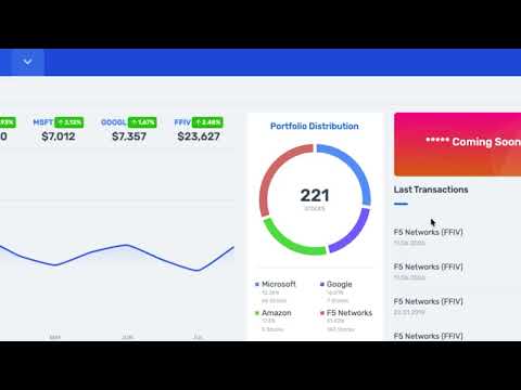 174Views3likes0Comments
Using F5 Distributed Cloud to solve cloud-native multi-regional application challenges
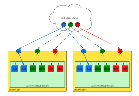
There are less-than-obvious costs to traditional multi-regional application availability, especially in micro-service or service-oriented architectures where regional failover has to be considered at a per-service level and not just in the context of the entire region. This can lead to significant transit charges with the cloud-native required approach. F5 Distributed Cloud is uniquely capable of solving these problems thanks to our combination of both network overlay and application-networking capabilities. This gets a little detailed, so here is a TL;DR version: Cloud-native architectures end up getting really expensive for service-level multi-regional failover because they require those services to be exposed on the internet for multi-regional failover. F5 Distributed Cloud (F5 XC) is a software defined network with embedded application load-balancing that makes service-level high-availability trivial. Details: Cloud-native multi-region redundancy strategies rely exclusively on DNS load-balancing solutions. Cloud applications that are hosted in multiple regions are advertised to the world with a DNS load-balancer resolving clients to healthy applications in different regions. Typically they send health-check probes to each service in each reason, and can either resolve these services/regions based on their availability, the IP geography of the requesting LDNS or DNS client, in an active-standby or active-active fashion. This has been known as Global Server Load Balancing (GSLB) and F5 pioneered this approach to build on the frailty of the Round-Robin DNS server approach that had been in place since the mid 90s. GSLB is a well-known pattern, but it does have its own challenges that must be considered: Failover times depend on the Time-To-Live (TTL) value that every DNS request supplies in its response. There is no control over what downstream resolvers rewrite this value to: The TTL value tells the DNS client (or intermediate LDNS recursive resolver) how long to cache the resolution response before sending a fresh query for the latest record of a hostname. In the case of GSLB for highly-available applications, a short TTL is desired because clients with existing cached resolution values will not resolve to the healthy server in a failover event until the cached value expires. The challenge is that a DNS administrator can’t control any downstream rewrites of TTL values that ISPs might do to lower the load on their DNS infrastructure. Lower TTLs mean increased resolution queries from clients, which increases their infrastructure requirements; rewriting this value to an hour or even a day lowers the load on their servers. Routing decisions based on HTTP request parameters are impossible with DNS because it operates completely independently of the HTTP protocol, and is therefore completely independent of application requests in general. This means that first, DNS must distribute traffic via record resolution with total ignorance of the requests and that the request-routing logic must be duplicated locally across all regions the application is deployed in. Specific to cloud-based, multi-regional, service-specific high-availability applications, DNS load-balancing requires that the services are exposed on the public internet. What makes this so painful is that often cloud architectures aren't as simple as a VPC/VNET/VCN with application servers/pods behind a public-facing native load balancer that directly proxies to applications in their native subnet (ex. Figure A); rather cloud-native transitive-routing services are often used to pass requests/responses through intermediate security inspection networks. This is becoming especially true in the era of agentic AI with its rapidly-growing sprawl of MCP services, agents, and agent harnesses along with local and third-party inference. The multiple transits through advanced enterprise cloud architectures add up exponentially thanks to the need to hairpin everything through the internet edge--even between local services--to facilitate GSLB-based multi-regional per-service high-availability, compounding transit costs. How does F5 Distributed Cloud address this problem? F5 XC moves multi-regional load-balancing back into the data-path by incorporating a software-defined network overlay into its capabilities. The F5 XC Customer Edge (CE) node is a local instantiation of the same software running in our Global Regional Edges (RE)--see Platform Overview for more information--and acts as both a proxy/load-balancer and a cloud router. This means on each CE, a VIP can be advertised for each service, while being able to discover and connect to origins in each cloud region, regardless of whether or not they are in the same cloud provider, private data center, or edge location. A service can reach other services advertised on these CEs, and in the event of a local failure of one service, F5 XC automatically routes to the other cloud region where another CE is located that has been actively health-checking its local instance of that service. This works even with IP overlap in one or more regions/clouds. F5 XC can even provide internet-facing VIPs that load-balance across these regions, including advanced request-based conditional routing. With the F5 XC secure mesh overlay, ordinarily difficult multi-regional/cloud networking becomes shockingly simple application networking. The complexity of networking and firewalling between locations is reduced to defining application VIPs in the desired sites on CEs, their application/service origins discovered by CEs, and any special conditional routing that is required as needed for that application. Instead of building interstate systems, application-specific teleportation portals handle inter-location communications and failovers automatically. This approach applies a minimal effort up front to implement an application-networking framework architecture (F5 XC) to rapidly reduce future application deployment time, failover time, and latency while increasing security by hiding services from the internet behind the F5 XC platform. It does all this while logging all requests and flows that traverse the platform by default, and provides advanced web application security and modern application discovery in Kubernetes along with traditional services running in IaaS services like cloud VMs or private cloud virtualization platforms.206Views1like0Comments
Automating TLS Certificates in Kubernetes with cert-manager and F5 Distributed Cloud DNS
Introduction If you run workloads in Kubernetes or Open Shift, you've almost certainly dealt with TLS certificates. You need them everywhere — Ingress controllers, internal services, mutual TLS between microservices, and API gateways. Managing them by hand is error-prone and doesn't scale: certificates expire silently, rotation is forgotten, and the person who originally created the wildcard cert is now working somewhere else. cert-manager solves this elegantly. It's a Kubernetes-native certificate controller that automates the issuance, renewal, and management of TLS certificates. It speaks ACME — the same protocol Let's Encrypt uses — but ACME is a standard, not a Let's Encrypt exclusive. You can point cert-manager at: Let's Encrypt (free, public, widely trusted) ZeroSSL, Buypass, Google Trust Services — other public CAs supporting ACME Step CA / HashiCorp Vault / Smallstep — for private PKI running inside your infrastructure Any commercial CA that has implemented an ACME endpoint This means the same workflow, the same Kubernetes manifests, and the same tooling can back both your public-facing services and your internal, corporate-signed certificates. One operator to rule them all. Why DNS-01 Challenge? ACME offers multiple ways to prove you own a domain. The most common is the HTTP-01 challenge, where the ACME server checks a well-known URL on your domain. It works well, but has limitations: The endpoint must be publicly reachable on port 80 It cannot issue wildcard certificates (*.example.com) The DNS-01 challenge takes a different approach: cert-manager (via a solver webhook) creates a _acme-challenge.example.com TXT record in your DNS zone. The ACME server checks for this record. Once verified, the TXT record is cleaned up automatically. Benefits: Works behind firewalls — no inbound HTTP needed Supports wildcard certificates — a single *.example.com certificate covers all subdomains Fully automated — the webhook handles record creation and deletion If your DNS is managed by F5 Distributed Cloud (F5 XC), you can now wire this entire flow together with the open-source cert-manager-webhook-f5xc solver. Architecture Overview Here's what happens when cert-manager issues a certificate using the F5 XC webhook: Developer applies Certificate manifest ▼ cert-manager creates Order + Challenge ▼ cert-manager calls webhook (DNS-01 solver) ▼ Webhook calls F5 XC DNS API → Creates TXT record: _acme-challenge.example.com ▼ ACME server (Let's Encrypt / other) validates the TXT record ▼ Webhook cleans up the TXT record ▼ cert-manager stores the issued certificate in a Kubernetes Secret The webhook runs as a standard Kubernetes Deployment inside your cluster, registered with cert-manager via a ValidatingWebhookConfiguration. It receives solver calls from cert-manager and translates them into F5 XC DNS API calls using an API token you provide as a Kubernetes Secret. Prerequisites Before we start, make sure you have the following in place: A Kubernetes cluster (1.21+) cert-manager installed (v1.14+) kubectl apply -f https://github.com/cert-manager/cert-manager/releases/latest/download/cert-manager.yaml Helm 3.8+ An F5 Distributed Cloud tenant with DNS management enabled Your domain's DNS zone managed in F5 XC F5 XC credentials for DNS API access — either an API Token or a Client Certificate (P12); see Step 1 below for details Least privilege note: The service account or user whose credentials you use must have permission to manage DNS records. As of the time of writing, the built-in role f5xc-dns-management-admin is sufficient. Avoid using tenant-admin or other overly broad roles — the webhook only needs to create and delete TXT records in your DNS zone. Step 1: Prepare F5 XC Credentials The webhook supports two authentication methods against the F5 XC DNS API: an API Token or a Client Certificate (P12). Both are stored as a Kubernetes Secret in the cert-manager namespace. Obtaining credentials in F5 XC Console Regardless of which method you choose, the service account must have sufficient permissions to manage DNS records. Follow the least-privilege principle: In the F5 XC Console, navigate to Account Settings → Administration. Create a dedicated service credential under IAM and assign it the f5xc-dns-management-admin role in the system namespace — this is the minimum required role as of the time of writing and grants access to DNS Zone Management without unnecessary privileges elsewhere in the tenant. Or use an existing account privileges under Personal Management credentials. Generate the credentials of your preferred type (API Token or API Certificate) Option A: API Token (simpler, recommended for most setups) Take the API Token obtained from the F5XC console and use it with the following command kubectl create secret generic f5xc-api-token \ --namespace cert-manager \ --from-literal=token=<YOUR_F5XC_API_TOKEN> Option B: Client Certificate (P12) F5 XC also supports certificate-based authentication using a P12 (PKCS#12) client certificate, which may be preferred in environments. Use the certificate and password generated in the previous step and store it as a Secret: kubectl create secret generic f5xc-client-cert \ --namespace cert-manager \ --from-file=certificate.p12=<PATH_TO_YOUR.p12> \ --from-literal=password=<P12_PASSWORD> Refer to the webhook documentation for the exact certificateSecretRef fields to use in the solver config when choosing this method. Verify the secret was created: kubectl get secret f5xc-api-token -n cert-manager Step 2: Install the Webhook via Helm The chart is published as an OCI artifact on GitHub Container Registry. Install it into the cert-manager namespace: helm install cert-manager-webhook-f5xc \ oci://ghcr.io/wenkow/charts/cert-manager-webhook-f5xc \ --namespace cert-managerbaba Check the rollout: kubectl rollout status \ deployment cert-manager-webhook-f5xc \ -n cert-manager kubectl get pods -n cert-manager Step 3: Configure a ClusterIssuer A ClusterIssuer tells cert-manager which ACME server to use and how to solve challenges. Here we're pointing it at Let's Encrypt production and configuring the F5 XC DNS-01 solver. Note on groupName: The field appears twice in the YAML below and serves different purposes. At the webhook level, it's a fixed identifier (acme.f5xc.io) that tells cert-manager which registered webhook to call. Inside config, it's the RRSet group name within your F5 XC DNS zone — a logical container for DNS records created by the webhook. You can choose any name; F5 XC will create the group if it doesn't exist. clusterissuer.yaml: apiVersion: cert-manager.io/v1 kind: ClusterIssuer metadata: name: letsencrypt-f5xc-prod spec: acme: email: [email protected] server: https://acme-v02.api.letsencrypt.org/directory privateKeySecretRef: name: letsencrypt-f5xc-prod-account-key solvers: - dns01: webhook: # Fixed identifier — tells cert-manager which webhook to call groupName: acme.f5xc.io solverName: f5xc config: # Your F5 XC tenant name (subdomain part of your console URL) tenantName: my-tenant # RRSet group name in F5 XC DNS zone groupName: "cert-manager" # ttl: 120 # optional, default is 120 seconds apiTokenSecretRef: name: f5xc-api-token key: token # If using certificate-based auth instead of a token, replace # apiTokenSecretRef with certificateSecretRef — see webhook docs. Apply it: kubectl apply -f clusterissuer.yaml Verify it's ready: kubectl get clusterissuer letsencrypt-f5xc-prod Step 4: Request a Certificate Now the fun part. Create a Certificate resource. Note that we're requesting both the apex domain and a wildcard — something that's only possible with DNS-01. certificate.yaml: apiVersion: cert-manager.io/v1 kind: Certificate metadata: name: example-tls namespace: default spec: secretName: example-tls issuerRef: name: letsencrypt-f5xc-prod kind: ClusterIssuer dnsNames: - example.com - "*.example.com" Apply it: kubectl apply -f certificate.yaml Step 5: Watch the Certificate Lifecycle This is where it gets satisfying to watch. cert-manager creates an Order, which spawns one or more Challenge objects. Each Challenge triggers the F5 XC webhook to create a DNS TXT record. Watch Certificate status kubectl get certificate example-tls -n default -w Inspect the Order kubectl get orders -n default kubectl describe order example-tls-1-3552197254 -n default Status: Authorizations: Challenges: Token: <token> Type: dns-01 URL: https://acme-v02.api.letsencrypt.org/acme/chall/... Identifier: example.com Initial State: valid URL: https://acme-v02.api.letsencrypt.org/acme/authz/... Wildcard: true Challenges: Token: <token> Type: dns-01 URL: https://acme-v02.api.letsencrypt.org/acme/chall/... Identifier: example.com Initial State: valid URL: https://acme-v02.api.letsencrypt.org/acme/authz/... Wildcard: false Certificate: REDACTED Finalize URL: https://acme-v02.api.letsencrypt.org/acme/finalize/... State: valid URL: https://acme-v02.api.letsencrypt.org/acme/order/... Events: Type Reason Age From Message ---- ------ ---- ---- ------- Normal Complete 8m37s cert-manager-orders Order completed successfully Inspect the Challenges before it's done kubectl get challenges -n default kubectl describe challenge example-tls-<1234567890> -n default Verify the Issued Certificate kubectl get secret example-tls -n default -o jsonpath='{.data.tls\.crt}' \ | base64 -d | openssl x509 -noout -text | grep -E "Subject:|DNS:|Not After" Not After : Aug 19 19:22:31 2026 GMT Subject: CN = example.com DNS:*.example.com, DNS:example.com Both the apex domain and the wildcard are covered by a single certificate. Using a Custom or Internal ACME Server One of the most powerful aspects of this setup is that the ACME server is completely configurable. If you run an internal CA — for example HashiCorp Vault with the ACME secrets engine, or Step CA — just change the server field in your ClusterIssuer: spec: acme: email: [email protected] server: https://vault.internal.example.com/v1/pki/acme/directory # or # server: https://step-ca.internal.example.com/acme/acme/directory The webhook doesn't care which ACME server you use — it only handles the DNS side of the challenge. This makes the setup equally useful for: Internet-facing services using Let's Encrypt Internal services using a corporate CA Mixed environments where different ClusterIssuer objects point to different CAs, all sharing the same F5 XC DNS solver Troubleshooting Tips Challenge stays in pending for a long time Check the webhook logs for API errors: kubectl logs -n cert-manager -l app=cert-manager-webhook-f5xc --tail=50 READY: False on ClusterIssuer Usually means cert-manager couldn't register an ACME account. Check that the email field is valid and the ACME server URL is reachable. TXT record not appearing in F5 XC - Verify that the credentials you stored in the Secret have the right DNS permissions. In F5 XC Console, check that the service account has the f5xc-dns-management-admin role (or equivalent). API token permission issues will typically surface as 403 Forbidden errors in the webhook logs. Summary The cert-manager-webhook-f5xc project closes the loop between F5 Distributed Cloud DNS and the Kubernetes-native certificate management ecosystem. With a few manifests and a Helm install, you get: Fully automated certificate issuance and renewal — no manual interventions, no expiry surprises Wildcard certificate support out of the box via DNS-01 ACME provider flexibility — works with Let's Encrypt, commercial CAs, or your internal PKI Clean Kubernetes-native UX — certificates are just resources; the entire lifecycle is observable with standard kubectl commands The webhook is open source, available on GitHub and packaged on Artifact Hub. Contributions and feedback are welcome. Related Resources cert-manager documentation cert-manager DNS01 webhook reference F5 Distributed Cloud DNS Management docs GitHub: Wenkow/cert-manager-webhook-f5xc Artifact Hub: cert-manager-webhook-f5xc339Views2likes1CommentCustomer Edge as a Fallback for F5 Distributed Cloud Regional Edge
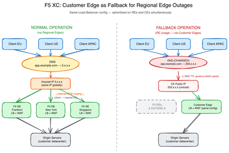
Introduction F5 Distributed Cloud Regional Edges (REs) form the backbone of F5’s globally distributed application delivery network. These F5-managed Points of Presence handle load balancing, Web Application Firewall (WAF) enforcement, bot protection, and API security for thousands of organizations worldwide. While F5 Regional Edges are engineered for extreme resilience—with built-in redundancy, geographic distribution, and continuous monitoring—no infrastructure is entirely immune to disruption. A defense-in-depth strategy demands that organizations consider even low-probability scenarios. This article explores how F5 Distributed Cloud Customer Edge (CE) nodes can serve as a fallback data path in the unlikely event of a Regional Edge outage, leveraging a capability that many organizations already have deployed but may not have considered for this purpose. Understanding the RE and CE Data Paths Regional Edge: The Default Path In a typical F5 Distributed Cloud deployment, application traffic follows this path: Client resolves the application’s FQDN via DNS DNS returns an F5 Regional Edge Anycast IP address Internet BGP routing directs the client to the nearest RE advertising that IP The RE terminates the connection, applies load balancing and security policies The RE forwards traffic to origin servers (directly or via CE nodes) The key mechanism here is IP Anycast. F5 Regional Edges advertise the same unicast IP address from multiple Points of Presence worldwide via BGP. When a client sends traffic to that IP, the internet’s BGP routing infrastructure naturally selects the shortest AS path—effectively directing the client to the geographically closest (or topologically nearest) RE. This means the DNS itself does not perform geographic selection. Every client worldwide receives the same IP address in the DNS response. It is the underlying BGP routing on the internet that ensures each client reaches its nearest RE. This is a fundamental difference from GeoDNS-based approaches, where different IPs are returned depending on the client’s location. Anycast routing typically delivers lower and more consistent latency than GeoDNS for several reasons: BGP routes on network topology, not geographic approximation. BGP is a path-vector protocol that selects routes based on AS path length, local preference, and policy attributes—not latency or congestion. However, in practice, routing to the topologically nearest PoP (fewest AS hops) generally correlates with reasonable latency, even if it is not optimized for it. GeoIP databases are approximations. GeoDNS relies on commercial GeoIP databases to map IP addresses to locations. These databases can be inaccurate or outdated. BGP doesn’t care about IP-to-location mapping; it routes based on actual network reachability. BGP adapts in real-time. If a link fails or a PoP goes offline, the BGP reconverges and traffic shifts to the next-best path automatically—often within seconds. GeoDNS is static until the DNS TTL expires. During that window, clients may continue hitting a degraded or unreachable endpoint. Regional Edges operate as a fully managed SaaS infrastructure. Organizations benefit from F5’s global Anycast network without deploying or maintaining edge nodes themselves. Customer Edge: The On-Premises Path Customer Edge nodes, typically deployed in on-premises data centers or customer cloud environments, can provide the same load balancing and WAF capabilities as Regional Edges. This is a critical but often underappreciated architectural property of the F5 Distributed Cloud platform. When a load balancer is configured in the F5 Distributed Cloud Console, it can be advertised on: Regional Edges only — the default for internet-facing applications Customer Edges only — common for internal applications Both Regional Edges and Customer Edges — the key to the fallback strategy described in this article The Shared Configuration Principle A single load balancer object in the F5 Distributed Cloud Console—with its full configuration including WAF policies, routes, rate limiting, and origin pools—can be advertised simultaneously on REs and CEs. There is no need to duplicate or maintain separate configurations. Aspect Regional Edge Customer Edge Load Balancing ✓ Same configuration ✓ Same configuration WAF / App Firewall ✓ Same policies ✓ Same policies Routes and Rewrites ✓ Same rules ✓ Same rules Origin Pool Selection ✓ Same pools ✓ Same pools Bot Defense ✓ ✓ API Protection ✓ ✓ Managed by F5 Customer Key Insight: This configuration parity is the foundation of the fallback strategy. The same security posture is enforced regardless of whether traffic enters through a RE or a CE. The Fallback Strategy: DNS-Based Traffic Switching How It Works The failover mechanism from Regional Edges to Customer Edges relies on a straightforward DNS change. Under normal operation, the application's DNS record points to the RE-assigned IP addresses. In a fallback scenario, the DNS record is updated to point to the public IP addresses of the Customer Edge nodes. Normal Operation: app.example.com → RE Anycast IP (e.g., 5.x.x.x, same IP globally) → BGP routing directs client to nearest Regional Edge → RE applies LB + WAF policies → RE forwards to origin Fallback Operation: app.example.com → CE Public IP (e.g., 203.0.113.10, standard unicast) → Client connects directly to Customer Edge (no Anycast routing) → CE applies the SAME LB + WAF policies → CE forwards to origin The application experience remains identical from the client's perspective in terms of security and functionality. The same policies are enforced, the same load balancing decisions are made, and the same origins are reached. The trade-off is that clients lose the Anycast proximity benefit—all traffic converges on the CE location(s) rather than being distributed to the nearest PoP. Prerequisites Before this strategy can be activated, several elements must be in place: The load balancer must be advertised on both REs and CEs. This is configured in the F5 Distributed Cloud Console under the load balancer's VIP advertisement settings. The CE advertisement must be active before an incident—configuring it during an outage adds delay and risk. The “Virtual Network“ type with value “ves-io-shared/public” is the equivalent of “Internet“ VIP advertisement. CE nodes must have public IP reachability. The CE's outside interface (or an NAT/firewall in front of it) must be reachable from the internet on the required ports (typically 443 and/or 80). This may require firewall rules, NAT configurations, or public IP assignments that should be validated in advance. CE nodes must have sufficient capacity for degraded-mode operation. Under normal operation, REs handle the full internet-facing traffic load. CEs used as fallback must be sized to sustain this traffic temporarily—long enough to bridge a RE outage, not to replace RE infrastructure indefinitely. This includes compute resources (CPU, memory), network bandwidth at the CE site, and upstream internet connectivity. DNS records must be prepared. The target CE IP addresses should be documented and ideally pre-staged in DNS management tooling so that the switchover can be executed rapidly. Important: All prerequisites must be validated before an incident occurs. A fallback strategy that hasn’t been tested is not a fallback strategy. Customer Edge: The On-Premises Path Customer Edge nodes, typically deployed in on-premises data centers or customer cloud environments, can provide the same load balancing and WAF capabilities as Regional Edges. This is a critical but often underappreciated architectural property of the F5 Distributed Cloud platform. When a load balancer is configured in the F5 Distributed Cloud Console, it can be advertised on: Regional Edges only — the default for internet-facing applications Customer Edges only — common for internal applications Both Regional Edges and Customer Edges — the key to the fallback strategy described in this article The Shared Configuration Principle A single load balancer object in the F5 Distributed Cloud Console—with its full configuration including WAF policies, routes, rate limiting, and origin pools—can be advertised simultaneously on REs and CEs. There is no need to duplicate or maintain separate configurations. Aspect Regional Edge Customer Edge Load Balancing ✓ Same configuration ✓ Same configuration WAF / App Firewall ✓ Same policies ✓ Same policies Routes and Rewrites ✓ Same rules ✓ Same rules Origin Pool Selection ✓ Same pools ✓ Same pools Bot Defense ✓ ✓ API Protection ✓ ✓ Managed by F5 Customer Key Insight: This configuration parity is the foundation of the fallback strategy. The same security posture is enforced regardless of whether traffic enters through a RE or a CE. DNS TTL: The Critical Factor Why TTL Matters The speed of a DNS-based failover is fundamentally governed by the Time-To-Live (TTL) value set on the application’s DNS records. TTL determines how long DNS resolvers and clients cache a DNS response before querying again. TTL Value Effective Switchover Time Trade-off 3600 (1 hour) Up to 1 hour Minimal DNS query load, slow failover 300 (5 minutes) Up to 5 minutes Moderate query load, reasonable failover 60 (1 minute) Up to 1 minute Higher query load, fast failover 30 (30 seconds) Up to 30 seconds Significant query load, near-instant failover Critical: TTL must be set before an incident occurs. Lowering TTL during an outage has no effect on records already cached by resolvers worldwide. The old, higher TTL continues to govern those cached entries until they expire naturally. Recommended Approach For organizations that consider CE fullbacks as part of their resilience strategy: Proactive TTL reduction: Set DNS TTL to 60–300 seconds on records that may need failover. This should be steady-state TTL, not an emergency change. Pre-incident preparation: Ensure the DNS change procedure is documented, tested, and can be executed by on-call staff within minutes. Automated failover (advanced): Integrate health checks on RE endpoints with DNS automation (via API calls to your DNS provider) to trigger the switch automatically. The TTL Reality Check Even with low TTL values, some clients and intermediate resolvers do not strictly honor TTL: Stub resolvers on end-user devices may cache beyond the stated TTL Some enterprise DNS resolvers impose minimum TTL floors (commonly 30–60 seconds) Browser DNS caches may hold entries independently of the OS resolver Connection keep-alive means existing TCP/TLS sessions continue to the old IP even after DNS changes Organizations should expect a gradual migration of traffic rather than an instantaneous cutover, even with aggressive TTL values. Plan for a transition window of several minutes during which traffic flows to both the old and new endpoints. Operational Caveats and Considerations Capacity Planning Under normal operations, Regional Edges absorb the full internet-facing traffic load across F5’s globally distributed infrastructure. Switching to Customer Edges concentrates this traffic onto a much smaller set of nodes, typically in one or two locations. Factor Regional Edges Customer Edges (Fallback) Geographic distribution Global Limited (customer sites) Bandwidth F5 backbone Customer uplink DDoS absorption F5 scrubbing capacity Customer/ISP capacity Horizontal scale Elastic Fixed (pre-provisioned) Recommendation: Conduct periodic load testing against CE nodes to validate they can sustain the expected RE traffic volume for a limited duration. CE infrastructure does not need to match RE capacity long-term, but it must hold up long enough to bridge an outage window without service degradation. DDoS Protection F5 Regional Edges benefit from F5’s network-level DDoS mitigation infrastructure. When traffic is redirected to Customer Edge nodes, this protection layer is bypassed. The CE site’s internet uplink becomes the direct target for any volumetric attack. Mitigation options: Ensure the CE site has upstream DDoS protection from the ISP or a dedicated scrubbing service Consider maintaining a DDoS-protected IP transit for CE public addresses If using BGP-routed DDoS protection, ensure CE public prefixes are covered Failover Workflow When a RE outage is confirmed and the decision to fail over is made, the procedure is: Step 1: Update DNS Records Change the application’s DNS A record (or AAAA for IPv6) from the RE IP addresses to the CE public IP addresses. If multiple CEs are available, configure multiple A records or use the BGP/ECMP architecture described in Part One of this series to distribute traffic across CEs behind a single public IP. Step 2: Monitor the Transition Observe traffic shifting to CEs as DNS caches expire. Expect a gradual ramp-up over a period aligned with your DNS TTL. Monitor CE resource utilization, error rates, and application response times. Step 3: Restore Normal Operation Once RE services are restored, reverse the DNS change to point back to RE IP addresses. Again, the transition back follows the same TTL-governed timeline. Validate that traffic has fully returned to the RE path before considering any CE-specific fallback infrastructure changes. Conclusion F5 Distributed Cloud Customer Edges provide a credible fallback path for the unlikely scenario of a Regional Edge outage. The platform’s ability to advertise a single load balancer—with identical configuration, WAF policies, and origin pools—on both REs and CEs is the enabling feature that makes this strategy viable without configuration duplication or drift. The key success factors are preparation and proactive configuration: DNS TTL must be set low before an incident, not during one CE capacity must be sufficient to handle traffic load in a degraded mode—this is a temporary measure, not a long-term replacement for RE infrastructure The full failover procedure must be tested periodically to remain viable Operational caveats—latency, DDoS exposure, session interruption—must be understood and accepted as part of the failover trade-off This approach does not replace the resilience built into F5’s Regional Edge infrastructure. Rather, it provides an additional layer of organizational confidence: even in a worst-case scenario, the application delivery path can be restored using infrastructure the organization already controls.471Views2likes0CommentsAI-Enabled Risk Scoring Helps Reduce Risks
Risk Categories AI-enabled Risk Scoring for F5 Distributed Cloud WAF reduces key risk categories: Security, Business/availability, and Operational. Security risk (missed attacks / false negatives): F5 Distributed Cloud's AI-Powered WAF Risk Scoring improves detection by combining multiple signals per request so you don't miss attacks that traditional WAFs may not catch: High-confidence signatures Curated signature combinations (with LLM labeling to improve precision) Attack indicators (e.g., SQLi signals, libinjection, multiple signatures) A real-time ML model—to catch attacks that traditional WAFs may miss Business/availability risk (false positives blocking real users) By assigning High/Medium/Low risk outcomes using layered analysis, teams can enforce blocking with more confidence and keep false positives low, reducing accidental customer impact such as blocking legitimate users. Staged workflows are enabled, such as: Block High Review Medium (implicitly allow Low while continuing to observe) Operational risk (slow time-to-protection and heavy tuning burden) F5 Distributed Cloud's AI-Powered WAF Risk Scoring reduces manual exceptions and case-by-case policy tuning, enabling teams to deploy the WAF in blocking mode sooner, with less ongoing friction across SecOps, dev, and platform teams. Outcome-based scoring enables: Improved consistency of enforcement across distributed apps/APIs Standardization of protection by reducing bespoke tuning per app How the system makes a risk decision Risk level is computed from layering multiple complementary analyses: High Risk or High Accuracy Signature matches Heuristics – such as injection attacks, multiple attack signatures detected, predictable resource exploitation, other risk indicators Neural network - Signatures can sometimes lead to false positives. To address that, a neural network acts as a secondary classifier to determine whether attack fragments flagged by signatures signal an attack, improving accuracy while maintaining real-time performance. Key system scope The ML model analyzes behavioral patterns to refine risk assessment, ensuring accurate classification and enabling effective threat prioritization. Calling the ML model will adhere to the following scope: The ML model is called only if at least one enabled (not excluded/disabled) signature triggers in these categories: Server-Side Code Injection, SQL Injection, XSS, Command Execution, Path Traversal, LDAP Injection, XPath Injection The model analyzes only HTTP request fragments that trigger signatures (not full raw requests). If signatures are excluded or disabled, they are not considered for invoking the model. Model output: 1 = malicious → request risk level set to High 0 = benign → request risk level set to False Positive A primer on Signature Accuracy vs Signature Risk Accuracy Indicates the ability of the attack signature to identify the attack including susceptibility to false-positive alarms: Low: Indicates a high likelihood of false positives. Medium: Indicates some likelihood of false positives. High: Indicates a low likelihood of false positives. Risk Indicates the level of potential damage this attack might cause if it is successful: Low: Indicates the attack does not cause direct damage or reveal highly sensitive data. Medium: Indicates the attack may reveal sensitive data or cause moderate damage. High: Indicates the attack may cause a full system compromise. Does AI-enabled Risk Scoring add latency? AI-enabled Risk Scoring works in line with F5 Distributed Cloud WAF, inspecting real-time traffic without adding noticeable latency in our tests.452Views1like0CommentsImplementing Risk-Based Actions with AI-Powered WAF: Customer Policy Paths
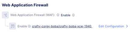
Why Custom policy is where risk-based actions matter most The default policy is straightforward: it applies a broad mix of signatures, threat campaigns, and violations; “Enhance with AI” is an optional add-on. Custom policies are where customers can accidentally recreate the same problems Risk Scoring is designed to solve—usually by combining: Overly broad/noisy signature selection (especially low-accuracy signatures) Aggressive enforcement (blocking Medium too early) Disabling/excluding key signatures and unintentionally reducing ML invocation So the rest of this blog is a tight, configuration-oriented walkthrough of the Custom path. Custom policy: configuration walkthrough (decision points → operational outcomes) Baseline: Navigate to the Custom controls LB Config → Web Application Firewall Create/edit the WAF object (Metadata `Name`, etc.) Set Security Policy = Custom Choose Signature Selection by Accuracy Optionally enable Enhance with AI (Risk Scoring) If enabled, optionally configure Action by Risk Score (risk-based enforcement) Step 1: Signature Selection by Accuracy (choose your baseline level) Accuracy indicates susceptibility to false positives: Low: high likelihood of false positives Medium: some likelihood of false positives High: low likelihood of false positives Note: This setting is foundational: it determines which signatures are active, and therefore the quality and volume of detection signals that feed into downstream risk evaluation. Operationally: High accuracy tends to support faster, safer enforcement. Medium/Low accuracy can expand coverage but increases the chance you’ll need exceptions, investigations, or staged rollout discipline. Step 2: Enhance with AI (turn on Risk Scoring) Enhance with AI = On enables AI-powered risk scoring and assigns each request a High/Medium/Low risk score using layered signals. Two implementation details to make explicit in your blog because they affect customer expectations: ML invocation depends on enabled signatures firing in the specified injection/execution categories. If teams disable/exclude those signatures, they may reduce when the model runs—changing practical behavior of risk evaluation. Step 3: Action by Risk Score (map risk levels to enforcement) When Action by Risk Score is enabled: By default, high-risk requests are blocked Users can choose whether Medium-risk requests are blocked (via dropdown) This is the primary knob that determines how quickly a user decides to move from “safe enforcement” to “broad enforcement.” Recommended rollout path: Day 0 → Day 7 → Steady state This is the most common and safest operational progression for customers Day 0 (safe enforcement baseline) Custom → Signature Selection by Accuracy = High (or High + Medium if you need broader coverage immediately) Enhance with AI = On Action by Risk Score = High Outcome Gets to blocking quickly while minimizing availability risk. High is blocked. This is the “prove safety while stopping obvious bad” posture. Day 7 (controlled expansion) Keep Custom + Enhance with AI + Action by Risk Score Optionally widen Signature Selection from High → High + Medium if coverage is insufficient Enhance with AI = On Action by Risk Score = High + Medium Outcome Expands detection inputs without immediately expanding enforcement. Teams focus on what’s landing in Medium and whether exclusions/disabled signatures are reducing ML invocation in key categories Steady state (mature enforcement) Custom → signature selection set to the broadest set Widen Signature Selection from High + Medium → High + Medium + Low Action by Risk Score = High + Medium Enhance with AI = On Action by Risk Score = High + Medium Outcome Risk outcomes become the enforcement interface. Broad, consistent blocking across apps/APIs with reduced per-app tuning and fewer signature-level decisions Common Pitfalls: Avoid Block Medium on Day 0 when including low-accuracy signatures—this is the fastest way to recreate false-positive outages. If you disable/exclude signatures in the key injection/execution categories, you can reduce ML invocation and change risk evaluation behavior. Summary Custom policies traditionally scale poorly because every app ends up with bespoke signature decisions and exception handling. Risk Scoring is designed to invert that: keep signatures as key signals but standardize enforcement via risk outcomes. If you implement Custom with the Day 0 → Day 7 → Steady state progression above, you get a predictable path from “block safely now” to “enforce broadly later” without returning to signature-by-signature tuning as your primary operating model.729Views2likes1CommentF5 Distributed Cloud – Why You Should Never Block Regional Edge IPs on Your Firewall
Introduction A common mistake when onboarding a public-facing application onto F5 Distributed Cloud (XC) is to restrict which source IP addresses can reach the origin server. Network and security teams, following a traditional “deny all / allow what you need” approach, sometimes allow only a handful of F5 XC Regional Edge IPs through their firewall — or worse, block RE IPs entirely because they see unfamiliar traffic hitting the origin from IP ranges they don’t recognize. This article explains why this is fundamentally incompatible with how F5 Distributed Cloud works, and what the consequences are. Understanding Distributed Architecture When you expose an application through F5 Distributed Cloud, the platform advertises your application’s FQDN via an Anycast IP address across all Regional Edges worldwide. As of the latest updates, this means your application is reachable through multiple REs across the Americas, Europe, and Asia-Pacific. Each RE acts as an independent proxy and point of presence. End users are routed to the closest RE based on BGP peering and network proximity. This is the core of F5 XC’s distributed model — there is no single centralized proxy. How Health Checks Work: Each RE Monitors Independently This is the critical point that is often misunderstood. When you configure a Health Check and an Origin Pool with your application’s public IP, every Regional Edge independently performs its own health check against your origin server. Each RE uses its own local internet breakout to reach your application — health check traffic does not traverse the F5 Global Network. This means: If you have an origin server with a public IP, and your Origin Pool is configured with “Public IP” (the default), then all REs will send health-check probes to your origin. Each RE maintains its own independent view of your origin’s health status. On the F5 XC console, you will see the same origin IP listed multiple times — once per RE — each with its own health status. The source IPs of these health checks come from the RE subnet ranges published in the official F5 documentation: F5 Distributed Cloud IP Address and Domain Reference. What Happens When You Block Some RE IPs Suppose you allow only a few RE IP ranges (for example, only European REs) but block the rest. Here is what happens: REs whose IPs are allowed will successfully complete health checks, and your origin will appear as UP from those locations. REs whose IPs are blocked will see health check failures, and your origin will be marked as DOWN from those locations. The immediate and most visible consequence is on the F5 XC console itself. Because a majority of REs report the origin as DOWN, the console will display a degraded application health status — showing poor availability and performance metrics. This gives a misleading picture of your application’s actual state: your origin is perfectly healthy, but the console reflects a largely unhealthy deployment simply because most REs cannot reach it through the firewall. This can trigger unnecessary troubleshooting, false alerts, and erode confidence in the platform’s monitoring data. Now, when an end user connects through a blocked RE (for example, a user in Asia hitting a Singapore RE), the platform behavior depends on the Endpoint Selection policy configured in your Origin Pool: Endpoint Selection Policy Behavior When Local RE Shows Origin as DOWN Local Endpoints Only Traffic is dropped. The user gets an error. No fallback. Local Endpoints Preferred (default) Traffic is forwarded via the F5 Global Network to a RE that has the origin marked as UP. This adds some latency. All Endpoints Same as Local Preferred — traffic is rerouted to a healthy RE over the Global Network. This can add major latency if the responding RE is far away from the origin. In the Local Endpoints Only case, users connecting through blocked REs will experience a complete outage for your application — even though the origin is healthy and reachable. In the Local Preferred or All Endpoints cases, the platform will attempt to reroute traffic through the F5 Global Network to a RE that has a healthy view of the origin. While the application will still be reachable, this introduces several problems: Increased latency: Traffic must travel from the ingress RE to a remote egress RE over the internal F5XC fabric before reaching your origin, instead of egressing locally to the internet. Suboptimal routing: A user in Tokyo may end up having their traffic routed through Paris because only European REs can reach the origin — defeating the purpose of a globally distributed edge. Reduced resilience: You’ve effectively reduced the number of egress points that can serve traffic, creating bottlenecks and potential single points of failure. The Correct Default Approach: Allowlist All RE IP Ranges The F5 official documentation is clear on this point: you should allowlist all F5 Distributed Cloud RE subnet ranges on your origin firewall. The published IP ranges are organized by region (Americas, Europe, Asia) and are available on the official F5 Distributed Cloud documentation page. Ideally, your origin firewall should be configured to only allow the F5 Distributed Cloud subnets for your application’s listening port. This ensures that: All RE health checks succeed, giving the platform an accurate and complete view of your origin’s health. Traffic egresses locally from the closest RE, providing the lowest latency path to your users. Only traffic routed through F5 XC can reach your origin, preventing attackers from bypassing the F5 XC security stack (WAAP, DDoS, Bot Protection, etc.) by hitting the origin directly. What If You Want to Limit Which REs Perform Health Checks? If you have a legitimate reason to reduce the number of REs performing health checks (for example, to reduce health check traffic on the origin or because your application is regionally scoped), F5 XC provides a built-in mechanism for this. Instead of using “Public IP” in the Origin Pool member configuration, select “IP Address of Origin Server on Given Sites” and then assign a Virtual Site that includes only the REs you want. For example, you could create a Virtual Site that includes only European REs, reducing your health check sources from all worldwide REs down to just the ones in that region. Conclusion F5 Distributed Cloud is architected as a fully distributed system. Health monitoring is not performed from a central location — it is performed independently by every Regional Edge. This design is what enables the platform to provide low-latency, resilient application delivery worldwide. Blocking RE IPs on your origin firewall fundamentally breaks this distributed health monitoring model. It causes health checks to fail, triggers suboptimal traffic routing, and potentially increases latency. The correct and recommended approach is to allowlist all F5 Distributed Cloud RE IP ranges on your origin firewall, and use the platform’s built-in Virtual Site mechanism if you need to control which REs perform health checks.312Views2likes1Comment
Help Needed: Tracking Unreachable Traffic and Public IPs in F5 XC
Hi all, I’m troubleshooting unreachable traffic in F5 XC and need to identify which Regional Edge (RE) locations cannot reach my backend servers (BE). Here are my questions: How can I track failed requests or unreachable servers in F5 XC? Are there specific logs or error codes (e.g., 503, 504) I should look for? Where can I find the public IPs of the REs trying to reach my backend servers? Any tips on monitoring backend server health and setting up alerts for when traffic can’t reach my backend? Appreciate any insights or resources! Thanks!446Views0likes2CommentsBulk-Create Secondary DNS Zones in F5 Distributed Cloud (via API)
If you’ve ever had to onboard dozens (or hundreds) of domains as secondary DNS zones in F5 Distributed Cloud (XC), you know the drill: click through the console, fill in the domain, add the primary server IP, save, repeat. It works - but it doesn’t scale. I ran into exactly this situation recently and figured a quick shell script would save me (and maybe you) a lot of clicking. What it does The script reads a simple text file - one domain per line, comma-separated with its primary DNS server IPs - and creates the corresponding secondary DNS zones via the F5 XC API. The input file looks like this: example.com, 10.0.0.1, 10.0.0.2 example.org, 192.168.1.1 internal.example.net, 172.16.0.1, 172.16.0.2, 172.16.0.3 Run the script, and it works through the list one by one: $ ./create_secondary_dns.sh Starting secondary DNS zone creation... Tenant : acmecorp --- [line 1] Creating secondary zone: example.com (primaries: 10.0.0.1 10.0.0.2) [line 1] OK - example.com created (HTTP 200) [line 2] Creating secondary zone: example.org (primaries: 192.168.1.1) [line 2] OK - example.org created (HTTP 200) --- Done. Success: 2, Failed: 0, Total lines: 2 That’s it. No Python, no Terraform, no extra frameworks - just bash, curl, and jq. TSIG support If your primary DNS servers require TSIG authentication for zone transfers, the script handles that too. Set the TSIG key name, algorithm, and secret in the configuration block, and the script will encrypt the secret locally using vesctl (the F5 XC CLI) before sending it to the API. If vesctl isn’t installed yet, the script downloads it automatically. If you don’t need TSIG, just leave the TSIG variables empty and the script skips that part entirely. Getting started 1. Clone the repo and navigate to the tool: git clone https://github.com/de1chk1nd/resources-and-tools.git cd resources-and-tools/tools/dns-secondary 2. Create your domain list: cp domains.txt.example domains.txt 3. Open the script and fill in your tenant name and API token: vi create_secondary_dns.sh 4. Run it: chmod +x create_secondary_dns.sh ./create_secondary_dns.sh The full README in the repository covers all configuration options, dependencies, and common error messages. What happens when something goes wrong? The script validates every line before hitting the API - domain names are checked for valid DNS characters, IP addresses are checked for valid IPv4 format. If a line is malformed, it’s skipped with a clear message and the script moves on to the next one. If a zone already exists in XC, the API returns a 409 and the script logs it as a failure but keeps going. At the end, you get a summary: how many succeeded, how many failed. A note on the repository This is a personal project, not an official F5 tool. It’s not supported by F5 and comes with no warranty. That said, it works well for my use cases and I hope it’s useful for yours too. If you run into issues or have suggestions, please open an issue on GitHub: GIT Repo The script lives here: DNS Tool511Views3likes1CommentUpdate an ASM Policy Template via REST-API - the reverse engineering way
I always want to automate as many tasks as possible. I have already a pipeline to import ASM policy templates. Today I had the demand to update this base policies. Simply overwriting the template with the import tasks does not work. I got the error message "The policy template ax-f5-waf-jump-start-template already exists.". Ok, I need an overwrite tasks. Searching around does not provide me a solution, not even a solution that does not work. Simply nothing, my google-foo have deserted me. Quick chat with an AI, gives me a solution that was hallucinated. The AI answer would be funny if it weren't so sad. I had no hope that AI could solve this problem for me and it was confirmed, again. I was configuring Linux systems before the internet was widely available. Let's dig us in the internals of the F5 REST API implementation and solve the problem on my own. I took a valid payload and removed a required parameter, "name" in this case. The error response changes, this is always a good signal in this stage of experimenting. The error response was "Failed Required Fields: Must have at least 1 of (title, name, policyTemplate)". There is also a valid field named "policyTemplate". My first thought: This could be a reference for an existing template to update. I added the "policyTemplate" parameter and assigned it an existing template id. The error message has changed again. It now throws "Can't use string (\"ox91NUGR6mFXBDG4FnQSpQ\") as a HASH ref while \"strict refs\" in use at /usr/local/share/perl5/F5/ASMConfig/Entity/Base.pm line 888.". An perl error that is readable and the perl file is in plain text available. Looking at the file at line 888: The Perl code looks for an "id" field as property of the "policyTemplate" parameter. Changing the payload again and added the id property. And wow that was easy, it works and the template was updated. Final the payload for people who do not want to do reverse engineering. Update POST following payload to /mgmt/tm/asm/tasks/import-policy-template to update an ASM policy template: { "filename": "<username>~<filename>", "policyTemplate": { "id": "ox91NUGR6mFXBDG4FnQSpQ" } } Create POST following payload /mgmt/tm/asm/tasks/import-policy-template to create an ASM policy template: { "name": "<name>", "filename": "<username>~<filename>" } Hint: You must upload the template before to /var/config/rest/downloads/<username>~<filename>". Conclusion Documentation is sometimes overrated if you can read Perl. Missed I the API documentation for this endpoint and it was just a exercise for me?635Views2likes8Comments