big-ip
1343 TopicsF5 BIG-IP Zero Trust Access
Introduction F5 BIG-IP Zero Trust Access, a key component of the F5 Application Delivery and Security Platform (ADSP), helps teams secure apps that are spread across hybrid, multi-cloud and AI environments. In this article, I’ll highlight some of the key features and use cases addressed by BIG-IP Zero Trust Access. F5 BIG-IP Zero Trust Access improves security and the user experience while managing access to your portfolio of corporate applications. Demo Video What is Zero Trust? Key Zero Trust Concepts Zero Trust is a cybersecurity framework built on the following core concepts: Never Trust Similar to human concepts that trust is not given freely, it is earned Always Verify Authenticate and authorize based on all available data points Continuously Monitor Zero Trust is an ongoing security framework that requires monitoring F5 enables zero-trust architectures that optimize your investments and extend zero-trust security across your entire portfolio. Why is this important? Securing apps is complex because apps are spread across a hybrid, multi-cloud environment. Apps themselves have become hybrid in nature, too. This creates 2 problems: Legacy and custom applications can complicate access security. Apps residing anywhere increases the attack surface. F5 BIG-IP Zero Trust Access secures hybrid application access. Securely managing access to corporate applications is critical to preventing data breaches. Doing it well can also increase efficiencies in business processes and user productivity. A Zero Trust security model can deliver this business value by enabling users to seamlessly and securely access their applications from anywhere regardless of where the application resides. In today’s world of hybrid, multicloud and AI applications, Zero Trust is a must. Application access control is key to any Zero Trust architecture. How does F5 address Zero Trust? F5 Zero Trust Begins with Secure Access to All Apps. The F5 Application Delivery and Security Platform (ADSP) is the foundation for Zero Trust Architectures. F5 ADSP delivers visibility, enforcement, and intelligence where it matters most: the application layer. While there are many important components to Zero Trust, we will be focusing on Zero Trust Application Access: Identity-Aware Proxy - Secure access to apps with a fine-grained approach to user authentication and authorization that enables only per-request context- and identity-aware access. Single Sign-On (SSO) and Access Federation - Integrating with existing SSO and identity federation solutions, users can access all their business apps via a single login, regardless of if the app is SAML enabled or not. OAuth 2.0 and OIDC Support - Enable social login to simplify access authorization from trusted third-party identity providers like Google, LinkedIn, Okta, Azure AD, and others. Identity Aware Proxy (IAP) – A Key Component of Zero Trust Use the Guided Configuration to configure the Identity Aware Proxy. From the BIG-IP UI, go to Access > Guided Configuration > Zero Trust. Select the Identity Aware Proxy You will see a configuration example of Identity Aware Proxy Click Next at the bottom For the Config Properties, give it a name, “IAP_DEMO” in this example Set the below options to On Click Save & Next Enable the F5 Client Posture Check Select your CA Trust Certificate Click Add Give it a Name, “FW_Check” in this example Under Windows, select Firewall and Domain Managed Devices Enter your domain name, “f5lab.local” in this example Click Done Click Save & Next Configure the Virtual Server Properties Switch Advanced Settings to On Set the Destination Address, “10.1.10.100” in this example For the Client SSL Profile, select the Client SSL Certificate, Private Key and Trusted Certificate Authorities For the Server SSL Profile, select your Server SSL Certificate and Private Key Click Save & Next Click Add under Authentication Give it a Name, “AD” in this example Set the Authentication Type to “AAA” Set the Authentication Server Type to Active Directory Choose your Authentication Server, “ad-servers” in this example Check the box for Active Directory Query Properties Under Required Attributes, find “memberOf” and click the arrow to move it to Selected Click MFA Click Add Double click Radius Under Choose Radius Server, select Create New Give it a name, “radius_pool” in this example Enter the Server IP Address, “10.1.20.8” in this example Enter the Secret in the two fields Click Save Click Save & Next Click Add Give it a name, “basic_sso” in this example For the SSO Configuration Object, click Create New The Username Source and Password Source should be set like the following Click Save Click Save & Next Under Applications click Add Give it a name, “iap1.acme.com” in this example Under Application Properties, set the FQDN and Caption to “basic.acme.com” Set the Pool IP Address to 10.1.20.7, Port 443, HTTPS Click Save For the Auth Domain, enter “iap1.acme.com” Click Save & Next Set Primary Authentication to “AD” Click Save & Next Click Add under Contextual Access For the Contextual Access Properties, give it a name, “basic.acme.com” in this example Set the Resource to iap1.acme.com Set Device Posture to FW_CHECK Set Single Sign-On to basic_sso Find the Sales Engineering Group and click Add Select the box for Additional Checks Set the Match Action to Step Up Set Step Up Authentication to Custom Radius based Authentication Click Save & Next The Remediation Page must be changed to a real host where users can download and install the EPI updates In this example, it has been changed to “https://iap1.acme.com/epi/downloads” Click Save & Next Click Save & Next Click Deploy Click Finish when the deployment completes Test the functionality by going to a client computer and accessing https://iap1.acme.com Logon with valid credentials You should see a page like the following Click basic.acme.com Login with valid credentials & click Validate You should see the basic.acme.com web page and be already logged in Note: If you disable the Windows Firewall on the client, you should get a block page similar to the following: Conclusion BIG-IP introduces a powerful access experience. BIG-IP provides a variety of Authentication, Federation, SSO and MFA protocols allowing for modern to legacy protocol translation. BIG-IP integrates with 3 rd parties to enforce identity aware decisions. BIG-IP secures identities for any apps and users anywhere in legacy and modern environments, spanning on-prem, hybrid or cloud locations. The highly scalable and proven Access Security solution that F5 customers know and trust. Related Content Zero Trust Solution Overview Secure Corporate Apps with a Zero Trust Security Model BLOG: F5 BIG-IP Zero Trust Access Zero Trust Application Access for Federal Agencies 117Views2likes0Comments
What's new in BIG-IP v21.0?
Introduction In November of 2025 F5 released the latest version of BIG-IP software, v21.0. This release is packed with fixes and new features that enhance the F5 Application Delivery and Security Platform (ADSP). These changes complement the Delivery, Security and Deployment aspects of the ADSP. Demo Video: New SSL Orchestrator Features SNI Preservation SNI (Server Name Indication) Preservation is now supported for Inbound Gateway Mode. This preserves the client’s original SNI information as traffic passes through the reverse proxy, allowing backend TLS servers to access and use this information. This enables accurate application routing and supports security workflows like threat detection and compliance enforcement. Previous software versions required custom iRules to enable this functionality. Note: SNI preservation is enabled by default. However, if you have existing Inbound Gateway Topologies, you must redeploy them for the change to take effect. iRule Control for Service Entry and Return Previously, iRules were only available on the entry (ingress) side, limiting customization to traffic entering the Inspection Service. iRule control is now extended to the return-side traffic of Inspection Services. You can now apply iRules on both sides of an Inspection Service (L2, L3, HTTP). This enhancement provides full control over traffic entering and leaving the Inspection Service, enabling more flexible, powerful, and fine-grained traffic handling. The Services page will now include configuration for iRules on service entry and iRules on service return. A typical use-case for this feature is what we call Header Enrichment. In this case, iRules are used to add headers to the payload before sending it to the Inspection Service. The headers could contain the authenticated username/group membership of the person who initiated the connection. This information can be useful for Inspection Services for either logging, policy enforcement, or both. The benefit of this feature is that the authenticated username/group membership header can be removed from the payload on egress, preventing it from being leaked to origin servers. New Access Policy Manager (APM) Features Expanded Exclusion Support for Locked Client Mode Previously, APM-locked client mode allowed a maximum of 10 exclusions, preventing administrators from adding more than 10 destinations. This limitation has now been removed, and the exclusion list can contain more than 10 entries. OAuth Authorization Server Max Claims Data Support The max claim data size is set to 8kb by default, but a large claim size can lead to excessive memory consumption. You must allocate the right amount of memory dynamically as required based on claims configuration. New Features in BIG-IP v21.0.0 Control Plane Performance and Scalability Improvements The BIG-IP 21.0.0 release introduces significant improvements to the BIG-IP control plane, including better scalability and support for large-scale configurations (up to 1 million objects). This includes MCPD efficiency enhancements and eXtremeDB scale improvements. AI Data Delivery Optimize performance and simplify configuration with new S3 data storage integrations. Use cases include secure ingestion for fine-tuning and batch inference, high-throughput retrieval for RAG and embeddings generation, policy-driven model artifact distribution with observability, and controlled egress with consistent security and compliance. F5 BIG-IP optimizes and secures S3 data ingress and egress for AI workloads. Model Context Protocol (MCP) support for AI traffic Accelerate and scale AI workloads with support for MCP that enables seamless communication between AI models, applications, and data sources. This enhances performance, secures connections, and streamlines deployment for AI workloads. F5 BIG-IP optimizes and secures S3 data ingress and egress for AI workloads. Migrating BIG-IP from Entrust to Alternative Certificate Authorities Entrust is soon to be delisted as a certificate authority by many major browsers. Following a variety of compliance failures with industry standards in recent years, browsers like Google Chrome and Mozilla made their distrust for Entrust certificates public last year. As such, Entrust certificates issued on or after November 12, 2024, are deemed insecure by most browsers. Conclusion Upgrade your BIG-IP to version 21.0 today to take advantage of these fixes and new features that enhance the F5 Application Delivery and Security Platform (ADSP). These changes complement the Delivery, Security and Deployment aspects of the ADSP. Related Content SSL Orchestrator Release Notes BIG-IP Release Notes BLOG F5 BIG-IP v21.0: Control plane, AI data delivery and security enhancements Press Release F5 launches BIG-IP v21.0 Introduction to BIG-IP SSL Orchestrator 990Views3likes0Comments
Introducing F5 Insight for ADSP
Introduction F5 Insight for ADSP, a key component of the F5 Application Delivery and Security Platform (ADSP), helps teams monitor and secure apps that are spread across hybrid, multi-cloud and AI environments. In this article, I’ll highlight some of the key features and use cases addressed by F5 Insight. F5 Insight: Actionable intelligence to foster operational excellence Demo Videos Demo Video: Introduction to F5 Insight for ADSP Demo Video: F5 Insight - A Closer Look What is F5 Insight for ADSP? F5 Insight is a holistic solution that unifies every aspect of operating applications. It provides end-to-end visibility and operational narratives. It allows you to prioritize to-dos with health scores, anomaly detection, and report cards. It delivers clarity and value faster with views built by F5 experts. It provides expert guidance and optimization recommendations using natural language interactions. F5 Insight is not intended to replace SIEM solutions like Splunk or Sentinel but serves a different, complementary purpose. It’s an open-source tool designed specifically for monitoring and analyzing metrics from your BIG-IP devices. By leveraging open-source telemetry tools, it collects and presents data in a central, easy-to-read dashboard. This eliminates the need to log into individual interfaces like the CLI or GUI to sift through logs and metrics, offering streamlined visibility into your BIG-IP estate for simplified monitoring and analysis. Why is F5 Insight important? Gain out-of-the-box actionable intelligence to optimize application delivery and security: Get critical application and infrastructure performance data, operational analytics, security issues, and other telemetry in a unified tool. Surface important KPIs and data points fast by querying data using natural language with model context protocol (MCP) support. Optimize application delivery and security, as well as underlying resources, with built-in F5 expertise and guidance. Share data with F5 and use F5 AI Data Fabric for application health scores, security grades, and automatic identification and categorization of apps by type and workload (In Limited Availability) Speeds mean-time-to-innocence (MTTI) and mean-time-to-restore (MTTR) with actionable intelligence and proactive alerts. Streamlines monitoring and analysis while being able to run on its own and integrate with your existing Grafana/VictoriaMetrics stacks. Leverage data to make the business case and prove ROI for more resources, application migrations, or system refreshes. How does F5 Insight work? F5 Insight is deployed as a Virtual Machine. This gives you full access and control of your F5 BIG-IP telemetry data. The configuration is simple, log into the F5 Insight portal and add your BIG-IP devices. There is no configuration needed on BIG-IP itself. Ready to get started? Log into the F5 Insight portal: By default you will arrive at the Home screen. From the navigation menu, under Manage, click BIG-IP Settings to add your BIG-IP devices. Before we add the BIG-IP devices click the Data Centers tab and then Add Data Center. This allows you to specify a location for the BIG-IP devices. Give it a Name, San Jose, CA in this example. Click Add Data Center. Go back to the Devices tab and click Add Device. Note that you can add a single device from here or add multiple devices using the Upload YAML Files (more on this later). For now, let’s add a single device using the management address or Endpoint, Username and Password. Scroll down and specify the Certificate Authority if using custom TLS certificates on BIG-IP devices. Under Data Center select the Data Center created previously, San Jose, CA in this example. Note: if you didn’t create a Data Center you can still do it now. Under Modules select the BIG-IP Modules you are using. In this example I selected Policy Firewall (or AFM). Click Add Device. The BIG-IP from San Jose has been added. From the navigation menu select BIG-IP Device then Device Overview to see more details. Note: you can select the specific Device you want to view. Important details are shown on this screen. Some items of interest are the BIG-IP version, system model or VM, Licenses and Enabled Modules. The Home Screen displays System Report Cards and allows you to drill down into the individual widgets. System Report Cards provide at-a-glance health indicators for four critical monitoring categories. Each card displays a status badge (Good, Warning, or Critical) based on deviation thresholds. Note: you can filter the Home Screen to display a specific Data Center. Adding Multiple BIG-IPs using YAML File Upload For bulk onboarding or infrastructure-as-code workflows, import devices using YAML configuration. Using YAML streamlines bulk onboarding, ensures consistency, improves scalability, simplifies automation, and increases accuracy. It also ensures integration with IaC workflows and CI/CD pipelines—enabling reusable, version-controlled configurations. From the BIG-IP Settings screen select Add Device. Upload your Defaults and Receiver YAML files here or click Paste YAML to copy/paste them. Note: YAML import also supports configuring F5 Insight features such as high availability, LLM Insights, AIDF, and data retention policies alongside device definitions. Both BIG-IPs are now connected to F5 Insight When you return to the BIG-IP Settings screen it should look like this: A correctly configured ast-defaults.yaml file will look like the following. Note: enter the username and password to log into your BIG-IPs A correctly configured ast-receivers.yaml file will look like the following. Note: enter a Device Name and Endpoint address. Conclusion F5 Insight for ADSP offers customizable visualizations and dashboards to help teams surface actionable metrics and KPIs tailored to your organization. It provides access to useful telemetry data for a deeper understanding of your environment, application behaviors, and complex BIG-IP deployments, all centralized in a single location. Identification of root causes during outages/tickets. Solves issues and struggles with Day 2 analysis of your BIG-IP Fleet and the applications therein. Mitigates the problem of a lack of detailed visual information on your BIG-IP Fleet. Set a foundation for the utilization of open-source tools and their benefits. Related Content F5 Insight for ADSP BLOG F5 Insight Documentation F5 Insight Product Page792Views3likes0CommentsHow to get a F5 BIG-IP VE Developer Lab License
(applies to BIG-IP TMOS Edition) To assist operational teams teams improve their development for the BIG-IP platform, F5 offers a low cost developer lab license. This license can be purchased from your authorized F5 vendor. If you do not have an F5 vendor, and you are in either Canada or the US you can purchase a lab license online: CDW BIG-IP Virtual Edition Lab License CDW Canada BIG-IP Virtual Edition Lab License Once completed, the order is sent to F5 for fulfillment and your license will be delivered shortly after via e-mail. F5 is investigating ways to improve this process. To download the BIG-IP Virtual Edition, log into my.f5.com (separate login from DevCentral), navigate down to the Downloads card under the Support Resources section of the page. Select BIG-IP from the product group family and then the current version of BIG-IP. You will be presented with a list of options, at the bottom, select the Virtual-Edition option that has the following descriptions: For VMware Fusion or Workstation or ESX/i: Image fileset for VMware ESX/i Server For Microsoft HyperV: Image fileset for Microsoft Hyper-V KVM RHEL/CentoOS: Image file set for KVM Red Hat Enterprise Linux/CentOS Note: There are also 1 Slot versions of the above images where a 2nd boot partition is not needed for in-place upgrades. These images include _1SLOT- to the image name instead of ALL. The below guides will help get you started with F5 BIG-IP Virtual Edition to develop for VMWare Fusion, AWS, Azure, VMware, or Microsoft Hyper-V. These guides follow standard practices for installing in production environments and performance recommendations change based on lower use/non-critical needs for development or lab environments. Similar to driving a tank, use your best judgement. Deploying F5 BIG-IP Virtual Edition on VMware Fusion Deploying F5 BIG-IP in Microsoft Azure for Developers Deploying F5 BIG-IP in AWS for Developers Deploying F5 BIG-IP in Windows Server Hyper-V for Developers Deploying F5 BIG-IP in VMware vCloud Director and ESX for Developers Note: F5 Support maintains authoritative Azure, AWS, Hyper-V, and ESX/vCloud installation documentation. VMware Fusion is not an official F5-supported hypervisor so DevCentral publishes the Fusion guide with the help of our Field Systems Engineering teams.110KViews14likes153CommentsAWS Transit Gateway Connect: GRE + BGP = ?
GRE and BGP are technologies that are... mature. In this article we'll take a look at how you can use AWS Transit Gateway Connect to do some unique networking and application delivery in the cloud. In December 2020 AWS released a new feature of Transit Gateway (TGW) that enables a device to peer with TGW via a GRE/BGP tunnel. The intent was to be used with SD-WAN devices, but we can also use it for things like load balancing many internal private addresses, NAT gateway, etc... In this article we'll look at my experience of setting up TGW Connect in a lab environment based on F5's documentation for setting up GRE and BGP. Challenges with TGW For folks that are not familiar with TGW it is an AWS service that allows you to stitch together multiple physical and virtual networks via AWS internal networking (VPC peering) or via network protocols (VPN, Direct Connect (private L2)). Using TGW you can steer traffic to a specific network device by creating a route table entry within a VPC that points to the device's ENI (network interface). This is useful for a case where you want to send all traffic for a specific CIDR (192.0.2.0/24) to traverse that device. In the scenario where a device is responsible for a CIDR it is also responsible for updating the route table for HA. This could be done via Lambda function, our Cloud Failover Extension, manual updates, etc.... The other downside is that this limits you to a single device per Availability Zone to receive traffic for that CIDR. TGW Connect provides a mechanism for the device to use a GRE tunnel/BGP to establish a connection to TGW and use dynamic routing protocols (BGP) to advertise the health of the device. This allows you to establish up to 4 devices to peer with TGW with up to 5 Gbps of traffic per connection (for comparison you can burst up to 50 Gbps with a VPC connection). Topology of TGW Connect When using TGW Connect it re-uses existing TGW connections. In practice this means that you are likely using an existing Direct Connect or VPC connection (I guess you could also use a VPN connection, but that would be weird). See also: https://aws.amazon.com/blogs/networking-and-content-delivery/simplify-sd-wan-connectivity-with-aws-transit-gateway-connect/ Configuring a BIG-IP for TGW Connect To use a BIG-IP with TGW Connect you will need a device that is licensed for BGP (also called Advanced Routing, part of Better/Best). Follow the steps for setting up TGW Connect and be sure to specify a different peer ASN than your TGW (you will need to use eBGP). The "Peer Address" will be the self-ip of the BIG-IP on the AWS VPC (when using a VPC). Configuring target VPC When setting up TGW Connect you will peer with an existing VPC. In the subnet that you want to use with TGW Connect (Peer Address of GRE tunnel) you will need to have a route that points to the TGW peer address; for example if you specify a CIDR of 10.254.254.0/24 for TGW and the peer address is 10.254.254.11 you will need to create a route that includes 10.254.254.0/24 on the subnet for BIG-IP peer address. Also make sure to open up Security Groups to allow GRE traffic to traverse to/from the interface that will be used for the GRE tunnel. The rule should allow the IP of the peer address (i.e. 10.254.254.11). Route to TGW from 10.1.7.0/24 GRE Tunnel On the BIG-IP under Network / Tunnels you will need to create a GRE Tunnel. You can use the default "gre" tunnel profile. Specify the same "Peer Address" that you used when setting up TGW Connect. You will also want to specify the Remote Address that is the TGW address. BGP Peer Next you will need to configure the BIG-IP to act as a BGP peer to TGW connecting over the GRE tunnel. TGW requires that you use an IP in the 169.254.0.0 range. This will require modify a db variable to allow that address to be used as a self-ip. The tmsh command to use is. modify sys db config.allow.rfc3927 { value "enable" } You can then create your BGP peer address to match the value that you used in TGW Connect. The BGP peer address will need to be configured to allow BGP updates (port 179). Since the traffic is occurring over the GRE tunnel there is no need to update AWS Security Groups (invisible to the ENI). Setting up BGP Peering TGW Connect requires eBGP to be used. The following is an example of a working config. This also assumes you go through the pre-req of setting up BGP/RHI. Be careful to only advertise the routes that you want, when you use "redistribute kernel" it will also advertise 0.0.0.0/0! Please also see: https://support.f5.com/csp/article/K15923612 ! no service password-encryption ! router bgp 65520 bgp graceful-restart restart-time 120 aggregate-address 10.0.0.0/16 summary-only aggregate-address 10.1.0.0/16 summary-only aggregate-address 10.2.0.0/16 summary-only aggregate-address 10.3.0.0/16 summary-only redistribute kernel neighbor 169.254.10.2 remote-as 64512 neighbor 169.254.10.2 ebgp-multihop 2 neighbor 169.254.10.2 soft-reconfiguration inbound neighbor 169.254.10.2 prefix-list tenlist out neighbor 169.254.10.3 remote-as 64512 neighbor 169.254.10.3 ebgp-multihop 2 neighbor 169.254.10.3 soft-reconfiguration inbound neighbor 169.254.10.3 prefix-list tenlist out ! ip prefix-list tenlist seq 5 deny 10.254.254.0/24 ip prefix-list tenlist seq 10 permit 10.0.0.0/8 ge 16 ! line con 0 login line vty 0 39 login ! end This example was created with help from a BGP expert Brandon Frelich. In the example above we only limiting routes to 3 CIDRs and configuring ECMP. At this point the BIG-IP could allocate VIPs on the CIDR, act as an AFM firewall, and if we used 0.0.0.0/0 it could act as an outbound gateway. Verifying the Setup You should be able to see your BGP connection go green in the AWS console and also see the status by running "show ip bgp neighbors" from imish. AWS Console ip-10-1-1-112.ec2.internal[0]>show ip bgp summary BGP router identifier 169.254.10.1, local AS number 65520 BGP table version is 4 2 BGP AS-PATH entries 0 BGP community entries Neighbor V AS MsgRcvd MsgSent TblVer InQ OutQ Up/Down State/PfxRcd 169.254.10.2 4 64512 293 293 4 0 0 00:47:08 3 169.254.10.3 4 64512 293 292 4 0 0 00:47:08 3 Total number of neighbors 2 Output from imish (tmos)# list /ltm virtual-address one-line ltm virtual-address 10.0.0.0 { address 10.0.0.0 arp disabled floating disabled icmp-echo disabled mask 255.255.0.0 route-advertisement selective traffic-group none unit 0 } ltm virtual-address 10.1.0.0 { address 10.1.0.0 arp disabled floating disabled icmp-echo disabled mask 255.255.0.0 route-advertisement selective traffic-group none unit 0 } ltm virtual-address 10.2.0.0 { address 10.2.0.0 arp disabled floating disabled icmp-echo disabled mask 255.255.0.0 route-advertisement selective traffic-group none unit 0 } (tmos)# list /net route tgw net route tgw { interface /Common/tgw-connect network 10.0.0.0/8 } Output from TMSH. Note route-advertisement is enabled on the virtual-addresses. We are using a static route to steer traffic to the GRE tunnel. You should also see any routes advertised as well. ECMP Considerations When you deploy multiple BIG-IP devices TGW can use ECMP to spray traffic across multiple devices (by enabling traffic group None or multiple standalone devices). Be aware that if you need to statefully inspect traffic you may want to enable SNAT to have the return traffic go to the same device or use traffic-group-1 to run in Active/Standby via Route Health Injection. Otherwise you will need to follow the guidance on setting up a forwarding virtual server to ignore the system connection table. Routing Connections One of the issues that a customer discovered when exploring this solution is that the BIG-IP will initially send health checks across the GRE tunnel using an IP from the 169.254.x.x address range, this follows the address selection criteria that a BIG-IP uses. One method of dealing with this is to assign an IP address in a range that you would like to advertise across the tunnel like 198.168.254.0/24. Creating a self-ip of 198.168.254.253 that you assign to the tunnel. To send traffic for a different range (i.e. 10.0.0.0/16) you can then create a static route on the BIG-IP that points to 198.168.254.1. Since the BIG-IP sees the address is on the tunnel it will correctly forward the traffic through the tunnel. Another question that arose was whether it was possible to have asymmetric traffic flows of utilizing both the GRE TGW Connect tunnel and the TGW VPC Connection of the VPC itself. I discovered that YES this is possible by following the guidance on enabling asymmetrically routed traffic. It hurts your brain a bit, but here's the results of a flow that is using both a Connect and VPC connection. You can do some crazy things, but with great power... Request traffic over VPC Connection Response traffic over TGW Connect (GRE) Other Options You could also achieve a similar result by using default VPC peering and making use of Cloud Failover Extension for updating the route table. The benefit of that approach is that you don't have to deal with GRE/BGP! It does limit you to a single device per-AZ vs. being able to get up to 4 devices running across a connection.7.4KViews2likes1CommentAccelerate your AI initiatives using F5 VELOS
Introduction F5 VELOS is a rearchitected, next-generation hardware platform that scales application delivery performance and automates application services to address many of today’s most critical business challenges. F5 VELOS is a key component of the F5 Application Delivery and Security Platform (ADSP). Demo Video High-Throughput and Concurrency for AI Data Ingestion Given the escalating data demands of AI training and inference pipelines, there is a critical need to architect object-based storage systems, such as S3, and corresponding clients in a manner that ensures high-throughput, scalability, and fault tolerance under massive parallel workloads. S3 Storage Systems increase scalability and resiliency by distributing data objects across multiple storage nodes, leveraging a unified “bucket” abstraction to streamline data organization, access, and fault tolerance. S3 Client Implementations employ highly parallelized, and multi-threaded operations to maximize data transfer rates and throughput, satisfying the low-latency, high-volume requirements of AI and other computationally intensive workloads. Performance and Security for AI Workloads F5 BIG-IP delivers multi-layer load balancing reinforced by robust in-flight security services and performance thresholds engineered to meet or exceed the most demanding enterprise-scale capacity requirements. F5 VELOS Chassis & Blades have advanced FPGA accelerators, high-performance CPU architectures, and cryptographic offload engines. They are all combined with scaling to multi-terabit throughput to meet or exceed the most demanding enterprise capacity requirements. F5 BIG-IP and VELOS enable high-performance data mobility and security for AI workloads anywhere. Load Balancing for S3 AI Training Data Replication Data Replication for Training AI model training and retraining often requires the replication of data from web-service-based object storage tiers to high-performance clustered filesystems. Market Constraints Tier-1 storage systems command high costs, and the ecosystem of certified providers for AI-specific architectures remains comparatively narrow. High-Performance Requirements Effective model training demands access to Tier-1 storage that supports hardware-accelerated data transfers, ensuring rapid delivery of input to GPU memory. S3 Based Migration Replication from cost-efficient, lower-performance storage repositories to Tier 1 infrastructure is commonly orchestrated via the S3 protocol to maintain both scalability and performance. Tiered Storage S3 AI Training Data Replication F5 BIG-IP and F5 Systems, rSeries and VELOS Distributed, high-volume, high-concurrency, and low-latency load balancing solutions engineered to optimize S3 AI training data replication. BIG-IP Best-In-Class Traffic Management & Security: SPEED Smart Load Balancing & Security Directs traffic to the optimal storage for performance, security, and availability. Seamless Data Flow BIG-IP LTM ensures efficient, secure routing from external sources to local storage. Optimized S3 Routing BIG-IP DNS directs client connections to highly available storage nodes for smooth data ingestion. BIG-IP Best-In-Class Traffic Management & Security: SCALE High-Throughput Traffic Management Optimize TCP and HTTPS flows for seamless object storage access. Accelerated Packet Processing Leverage embedded eVPA in FPGA for high-performance L4 IPv4 throughput. Crypto Offload for Speed BIG-IP LTM offloads encryption to best-in-class hardware on rSeries and VELOS, boosting performance. BIG-IP Best-In-Class Traffic Management & Security: Security Robust DDoS Protection BIG-IP’s AFM defends against volumetric and targeted attacks. Secure Traffic Management BIG-IP LTM ensures efficient, secure routing from external sources to local storage. End-to-End Data Protection Safeguards AI workloads with policy-driven security and threat mitigation. F5 Systems Enables Accelerated AI Application Delivery F5 VELOS, rSeries, and BIG-IP Enable distributed, high-volume, high-concurrency, low-latency application delivery for S3. The All-New VELOS CX1610 Provides the multi-terabit throughput necessary for high-performance traffic orchestration. F5 BIG-IP App Services Suite Simplify and secure application delivery for the most demanding high-throughput AI infrastructure needs. Conclusion Unleash Massive Throughput The All-New VELOS BX520 Blade The All-New VELOS CX1610 Chassis Related Articles F5 VELOS: A Next-Generation Fully Automatable Platform F5 rSeries: Next-Generation Fully Automatable Hardware Realtime DoS mitigation with VELOS BX520 Blade DEMO: The Next Generation of F5 Hardware is Ready for you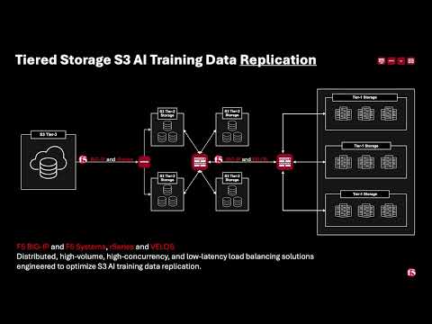 507Views3likes0Comments
BIG-IP for Scalable App Delivery & Security in Hybrid Environments
Scope As enterprises deploy multiple instances of the same applications across diverse infrastructure platforms such as VMware, OpenShift, Nutanix, and public cloud environments and across geographically distributed locations to support redundancy and facilitate seamless migration, they face increasing challenges in ensuring consistent performance, centralized security, and operational visibility. The complexity of managing distributed application traffic, enforcing uniform security policies, and maintaining high availability across hybrid environments introduces significant operational overhead and risk, hindering agility and scalability. F5 BIG-IP Application Delivery and Security address this challenge by providing a unified, policy-driven approach to manage secure workloads across hybrid multi-cloud environments. It can be used to scale up application services on existing infrastructure or with new business models. Introduction This article highlights how F5 BIG-IP deploys identical application workloads across multiple environments. This ensure high availability, seamless traffic management, and consistent performance. By supporting smooth workload transitions and zero-downtime deployments, F5 helps organizations maintain reliable, secure, and scalable applications. From a business perspective, it enhances operational agility, supports growing traffic demands, reduces risk during updates, and ultimately delivers a reliable, secure, and high-performance application experience that meets customer expectations and drives growth. This use case covers a typical enterprise setup with the following environments: VMware (On-Premises) Nutanix (On-Premises) OCP (On-Premises) Google Cloud Platform (GCP) Solution Overview The following video shows how F5 BIG-IP VE running on different virtualized platforms and environments can be configured to scale, secure, and deliver applications equally, even when located on-prem and in cloud environments. By providing a uniform interface and security policies organizations can focus on other priorities and changing business needs. Architecture Overview As illustrated in the diagram, when new application workloads are provisioned across environments such as AWS, GCP, VMware (on-prem), Nutanix (on-prem & VMware) BIG-IP ensures seamless integration with existing services. Platforms Supported Environments VMware On-Prem, GCP, Azure Nutanix On-Prem, AWS, Azure OCP On-Prem, AWS, Azure This article outlines the deployment in VMware platform. For deployment in other platforms like Nutanix and GCP, refer the detailed guide below. F5 Scalable Enterprise Workload Deployments Complete Guide Scalable Enterprise Workload Deployment Across Hybrid Environments Enterprise applications are deployed smoothly across multiple environments to address diverse customer needs. With F5’s advanced Application Delivery and Security features, organizations can ensure consistent performance, high availability, and robust protection across all deployment platforms. F5 provides a unified and secure application experience across cloud, on-premises, and virtualized environments. Workload Distribution Across Environments Workloads are distributed across the following environments: VMware: App A & App B OpenShift: App B Nutanix: App B & App C → VMware: Add App C → OpenShift: Add App A & App C → Nutanix: Add App A Applications being used: A → Juice Shop (Vulnerable web app for security testing) B → DVWA (Damn Vulnerable Web Application) C → Mutillidae Initial Infrastructure & B, Nutanix: App B &C, GCP: App B. VMware In the VMware on-premises environment, Applications A and B are deployed and connected to two separate load balancers. This forms the existing infrastructure. These applications are actively serving user traffic with delivery and security managed by BIG-IP. Web Application Firewall (WAF) is enabled, which will prevent any malicious threats. The corresponding logs can be found under BIG-IP > Security > Event Logs Note: This initial deployment infrastructure has also been implemented on Nutanix and GCP. For the full details, please consult the complete guide here Adding additional workloads To demonstrate BIG-IP’s ability to support evolving enterprise demands, we will introduce new workloads across all environments. This will validate its seamless integration, consistent security enforcement, and support for continuous delivery across hybrid infrastructures. VMware Let us add additional application-3 (mutillidae) to the VMware on-premises environment. Try to access the application through BIG-IP virtual server. Apply the WAF policy to the newly created virtual server, then verify the same by simulating malicious attacks. Nutanix The use case described for VMware is equally applicable and supported when deploying BIG-IP on Nutanix Bare Metal as well as Nutanix on VMware. For demonstration purposes, the Nutanix Community Edition hypervisor is booted as a virtual machine within VMware. Inside this hypervisor, a new virtual machine is created and provisioned using the BIG-IP image downloaded from the F5 Downloads portal. Once the BIG-IP instance is online, an additional VM hosting the application workload is deployed. This application VM is then associated with a BIG-IP virtual server, ensuring that the application remains isolated and protected from direct external exposure. OCP The use case described for VMware is equally applicable and fully supported when deploying BIG-IP with Red Hat OpenShift Container Platform (OCP) including Nutanix and VMware-based infrastructures. For demonstration, OCP is deployed on a virtualized cluster, while BIG-IP is provisioned externally using an image from the F5 Downloads portal. BIG-IP consumes the OpenShift configuration and dynamically creates the required virtual servers, pools, and health monitors. Traffic to the application is routed through BIG-IP, ensuring that the application remains isolated from direct external exposure while benefiting from enterprise-grade traffic management, security enforcement, and observability. GCP (Google Cloud Platform) The use case discussed above for VMware is also applicable and supported when deploying BIG-IP on public cloud platforms such as Azure, AWS, and GCP. For demonstration purposes, GCP is selected as the cloud environment for deploying BIG-IP. Within the same project where the BIG-IP instance is provisioned, an additional virtual machine hosting application workloads is deployed and associated with the BIG-IP virtual server. This setup ensures that the application workloads remain protected behind BIG-IP, preventing direct external exposure. Key Resources: Please refer to the detailed guide below, which outlines the deployment of Nutanix on VMware and GCP, and demonstrates how BIG-IP delivers consistent security, traffic management, and application delivery across hybrid environments. F5 Scalable Enterprise Workload Deployments Complete Guide Conclusion This demonstration clearly illustrates that BIG-IP’s Application Delivery and Security capabilities offer a robust, scalable, and consistent solution across both multi-cloud and on-premises environments. By deploying BIG-IP across diverse platforms, organizations can achieve uniform application security, while maintaining reliable connectivity, strong encryption, and comprehensive protection for both modern and legacy workloads. This unified approach allows businesses to seamlessly scale infrastructure and address evolving user demands without sacrificing performance, availability, or security. With BIG-IP, enterprises can confidently deliver applications with resilience and speed, while maintaining centralized control and policy enforcement across heterogeneous environments. Ultimately, BIG-IP empowers organizations to simplify operations, standardize security, and accelerate digital transformation across any environment. References F5 Application Delivery and Security Platform BIG-IP Data Sheet F5 Hybrid Security Architectures: One WAF Engine, Total Flexibility Distributed Cloud (XC) Github Repo BIG-IP Github Repo 508Views2likes0Comments


