verified designs
214 TopicsSingle-click CDN Experience for F5 Distributed Cloud Load Balancers
Fundamentals The modern CDN has evolved well beyond cache and serve. Today’s platforms are intelligent edge fabrics that combine performance optimization, layered security, multicloud routing, and even workload execution at the edge. Few products embody this evolution more completely than F5 Distributed Cloud CDN, and this post explores both why CDNs matter and what sets F5’s newest approach apart. At its core, a CDN is a globally distributed system of edge servers, called PoPs or Regional Edges (RE), that cache content and handle user requests on behalf of the server origin. When a user requests a resource, DNS resolution routes them to the nearest PoP. If the resource is cached there (a “cache hit”), it’s returned immediately. If not (a “cache miss”), the PoP fetches it from the origin, stores it, and returns it to the user. The speed improvement isn’t just perceptual. Reduced Round-Trip Time (RTT) correlates directly with business outcomes. Every page load shaved makes a difference for search rankings, checkout completion, and ad viewability all improve with lower latency. CDNs don’t just make things faster; they make digital businesses more competitive. To put the difference in concrete terms, here’s how a typical 200KB page might deliver across different scenarios. Platform deep dive Traditional CDNs optimize for one thing: getting cached bytes to users fast. Distributed Cloud CDN starts there but doesn’t stop, it's engineered as a unified platform where content delivery, application security, multicloud connectivity, and edge compute converge under a single operational surface. F5’s approach is architecturally distinct Most CDNs are standalone services that organizations integrate with separate security tools, load balancers, and observability stacks. The operational overhead of stitching these together and keeping policies consistent across them is substantial. F5 takes a different approach: CDN is one capability within the broader Distributed Cloud Platform, meaning it inherits the platform’s DNS, load balancing, WAF, observability, and multicloud networking services. The practical result, noted by enterprise users, is that WAF rules, DDoS policies, and CDN configurations all live in the same console. There’s no context switching between vendors, no policy drift between your security tool and your delivery tool, and no blind spots at the handoff between them. In the newest product update, anyone already using a Distributed Cloud Load Balancer can enable CDN acceleration with a single click: no rearchitecting, no new deployments. Built-in cacheability insights estimate performance improvement and cost savings before activation, so teams can make informed decisions without guesswork. Target use cases: Where F5 Distributed Cloud CDN fits best There are three primary use-case families for enabling an integrated CDN: Secure apps everywhere (WAAP + CDN): Organizations that need comprehensive web app and API protection with WAF, DDoS, bot defense, unified content delivery under a single policy plane and management console. Modern digital experiences: Dynamic, personalized applications spanning multiple public clouds, edge locations, and on-premises infrastructure that need consistent delivery regardless of where origin workloads live. Multicloud & edge initiatives: Enterprises migrating workloads across cloud providers or deploying edge compute who need a platform that bridges delivery, security, and service mesh without re-platforming for each environment. Visibility & Control: You can’t optimize what you can’t see F5’s Distributed Cloud Platform ships with unified observability that spans delivery performance and security posture. Real-time dashboards expose traffic patterns, cache efficiency metrics, origin health, and security event timelines, all from the same interface used to configure policies. Cache efficiency isn’t a static attribute either. Distributed Cloud CDN provides granular control over cache keys, TTL values, and path or header-based caching rules, enabling teams to optimize hit rates for specific content types and access patterns. Cacheability insights indicate which web apps are candidates for acceleration. For security operations, the edge generates rich telemetry: request rates, blocked attack types, geographic traffic distribution, and bot classification outcomes. This feeds into the same observability layer as performance data, giving teams a single pane of glass rather than separate dashboards for CDN and security. The recently announced F5 Insight capability extends this further, bringing OpenTelemetry-powered observability across BIG-IP, NGINX, and Distributed Cloud Services, consolidating performance and security intelligence across an organization’s entire F5 footprint into actionable, unified visibility. Demo Walkthrough Final thoughts A CDN is no longer an optimization. It’s table stakes for any organization serving digital experiences to a geographically distributed audience. The question isn’t whether to deploy one, but which platform best aligns with the complexity of your architecture and the ambition of your security posture. For organizations operating at the intersection of multicloud delivery, API-driven applications, and enterprise security requirements, Distributed Cloud CDN represents a compelling architectural choice: a platform that treats performance and security not as separate concerns to be stitched together, but as integrated properties of the same edge fabric. The bytes will always need to get from somewhere to your users. F5 makes that journey faster, safer, and smarter. Additional Resources Product information: https://www.f5.com/products/distributed-cloud-services/cdn Technical documentation: https://docs.cloud.f5.com/docs-v2/content-delivery-network/how-to/cdn-mgmt/conf-cache-lb Feature announcement blog: https://www.f5.com/company/blog/f5-distributed-cloud-cdn-faster-apps-one-click-enablement-lower-costs 284Views1like0Comments
KASM Workspaces Integration with F5 BIG-IP Zero Trust Access (formerly APM)
Introduction F5 BIG-IP Zero Trust Access, a key component of the F5 Application Delivery and Security Platform (ADSP), helps teams secure apps that are spread across hybrid, multi-cloud and AI environments. In this article, I’ll show you how to secure your Kasm Workspace using F5 BIG-IP Zero Trust Access. Kasm Workspaces Kasm Workspaces is a containerized streaming platform designed for secure, web-based access to desktops, applications, and web browsing. It leverages container technology to deliver virtualized environments directly to users' browsers, enhancing security, scalability, and performance. Commonly used for remote work, cybersecurity, and DevOps workflows, Kasm Workspaces provides a flexible and customizable solution for organizations needing secure and efficient access to virtual resources. As noted in the Kasm Documentation, the Kasm Workspaces Web App Role servers should not be exposed directly to the public. That’s where F5 BIG-IP Zero Trust Access can help. Demo Video Deployment Prerequisites F5 BIG-IP version 17.x Zero Trust Access version 10.x Kasm Workspaces version 1.17 installed and configured properly Configure using Automation Toolchain with AS3 and FAST Templates The F5 BIG-IP Automation Toolchain is a suite of tools designed to automate the deployment, configuration, and management of F5 BIG-IP devices. It enables efficient and consistent management using declarative APIs, templates, and integrations with popular automation frameworks. Application services (FAST) templates are predefined configurations that streamline the deployment and management of applications by providing consistent and repeatable setups. NOTE: The configuration using the Automation Toolchain is well-documented in this DevCentral article, which also includes demo videos: How I did it - “Delivering Kasm Workspaces three ways” Configure Manually Using a Virtual Server This article will focus on the manual configuration of the BIG-IP using a Virtual Server. Configuring it this way will give you a deeper understanding of how all the components work together to create a cohesive solution. Network Environment Linux “External” client IP: 10.1.10.4 BIG-IP “External” Self IP: 10.1.10.10 BIG-IP “Internal” Self IP: 10.1.20.10 Kasm Workspace IP: 10.1.20.23 BIG-IP Configuration Create HTTP Monitor: First, let’s create the HTTP Monitor for the Kasm Workspace server. From Local Traffic > Monitors > click the green plus sign to add a new one. Give it a name, “Kasm-Monitor” in this example Set the Type to HTTP Enter the following for the Send String: GET /api/__healthcheck\r\n Enter the following for the Receive String: OK It should look like this: Set Reverse to Yes and click Finished Create Pool: Next we’ll create the Pool From Local Traffic > Pools > Pool List > click the plus sign to add a new one Give it a name, “Kasm-Pool” in this example Select the Health Monitor you created previously and click the arrows to move it to Active Under Resources specify a Node Name, “Kasm-Server” in this example Specify the IP Address, “10.1.20.23” in this example Set the Service Port to 443, then click Add Click Finished Create Virtual Server: Next we’ll create the Virtual Server From Local Traffic > Virtual Servers > Virtual Server List > click the plus sign to add a new one Give it a Name, “vs_kasm” in this example. Keep the Type as Standard. Set the Destination to the IP Address you want the BIG-IP to listen on for connections to the Kasm server, “10.1.10.100” in this example. Set the Service Port to HTTPS, port 443. Click Finished at the bottom Click on the Virtual Server you just created Click Resources Set the Default Pool to kasm_pool, then click Update The Kasm Virtual Server Status should eventually change to Green when the Health Monitor is successful. NOTE: The Virtual Server configuration in this example has been simplified for demonstration purposes. Additional configuration options will be covered later in this article. Kasm Workspaces Configuration The Kasm Workspace will need a Zone configured with the default settings. Login as Admin and check this from Infrastructure > Zones. You will need at least one Workspace. In this example, I have a Workspace with Chrome, Firefox, Terminal and Ubuntu Jammy Click the WORKSPACES Tab at the top of the screen to see what the Workspace looks like Your view should look like this: Test Kasm Workspaces Login as a User NOTE: The IP Address used to connect to the Kasm Workspaces through the BIG-IP is the Virtual Server listening IP Address 10.1.10.100 When the Workspace loads, click Firefox Choose the option to Launch Session in a new Tab After a moment, Firefox will load Here you can see the F5.com website displayed NOTE: The browser pop-up blocker can prevent the Kasm Workspace applications from successfully launching. You can disable the pop-up blocker or create an exception for the BIG-IP Virtual IP (10.1.10.100). Enable SSL Decryption Enabling SSL Decryption allows you to fully inspect the requests and payloads passing through BIG-IP. From Local Traffic > Virtual Servers > click Virtual Server List Then click the name of your Virtual Server, “vs_kasm” in this example In the Configuration section, set the Protocol Profile (Client) to http Set the SSL Profile (Client) to clientssl Set the SSL Profile (Server) to serverssl NOTE: If you have created your own Client and Server SSL Profiles, you should add them here. The instructions above are for demonstration purposes only. Scroll to the bottom and click Update You’re done! Conclusion F5 BIG-IP Zero Trust Access is a key asset to securing containerized platforms like KASM Workspaces. In this article, you learned how to secure your Kasm Workspace using F5 BIG-IP Zero Trust Access. Related Content How I did it - “Delivering Kasm Workspaces three ways” Download Kasm Workspaces Kasm Documentation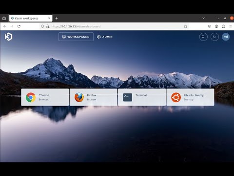 314Views2likes0Comments
Integrating External Connectors in Distributed Cloud: IPSec, BGP, & Routing Policy with AWS & Cisco
Introduction As multi‑cloud architectures continue to grow, organizations increasingly need consistent, secure, and efficient connectivity between disparate environments. Linking private data centers, cloud VPC's, third‑party virtual routers, enterprise SD‑WAN domains and partner networks, hybrid connectivity must be reliable, automated, and operationally simple to manage. In this technical article, we’ll explore F5’s new external segment connector specifically designed for edge networks. We’ll focus on the setup process, connectivity testing, and explore the benefits of this solution with a robust example deployment. External Connectors bridge Customer Edge (CE) sites with third‑party edge devices such as Cisco CSR and 8000v routers, using standards‑based IPSec VPN and BGP. This simplifies multi‑cloud and hybrid routing in complex environments and can also be used to integrate enterprise SD‑WAN routing domains and to securely connect to partner networks. This article provides an overview of building IPSec and BGP connections between a F5 CE instance in AWS and a Cisco 8000v router to connect VPC A to VPC B without using VPC peering or a Transit Gateway (TGW). We’ll then share an example of applying BGP routing policy for inbound route control. Solution: External Connectors At a high level, the goal of the solution is to: Establish IPSec VPN between a F5 CE site and a Cisco 8000v router. Bring up BGP peering over the IPSec tunnel. Apply and validate routing policy for inbound route filtering. This example topology has a CE in AWS VPC A located on the right, with two interfaces: Site Local Outside (SLO) and Site Local Inside (SLI). There is a workload behind the CE for end-to-end connectivity tests. The third-party device is a Cisco 8000v router that lives on AWS in VPC B. This device also has two interfaces, and there is a virtual machine behind the Cisco router. To summarize, this includes: CE AWS Site in VPC A, with SLO and SLI interfaces and a workload behind it. Cisco 8000v router in VPC B, with GigabitEthernet1 and GigabitEthernet2, plus a VM behind it. Traffic between the two VPCs must traverse a public IP path due to the absence of VPC peering or a TGW with attachments. This solution uses a Streamlined IPSec Configuration, F5 CE’s support pre‑built IKEv2 Phase 1 and Phase 2 profiles, drastically reducing the setup time for standard IPSec tunnels. While administrators retain the freedom to define custom profiles, the default templates accelerate configuration and limit the risk of mismatch‑related failures. With Consistent Multi‑Cloud Routing running BGP directly over IPSec, the CE’s ensure dynamic routes exchange across hybrid environments, replacing static routing with scalable and distributed control. Enabling visibility with built-in troubleshooting, the following observability features accelerate change validation and incident resolution. CE’s support deep diagnostic tools and include the following: Tunnel and BGP status dashboards Node‑level status granularity CLI tools for BGP (show ip bgp, summaries, advertised routes) Route tables filtered by protocol source Real‑time tunnel throughput metrics Administrators can now enforce consistent inbound and outbound routing behavior across distributed sites. New BGP Routing Policies allow fine‑grained control including: IP Prefix‑lists, Community tags, AS‑path matching, and Actions including allow, deny, MED, local-preference, etc. Demo Highlights 1. Establish IPSec VPN Connectivity Utilize the pre-created default IKE Phase 1 and Phase 2 profiles for streamlined configuration. Both CE and Cisco configurations rely on correctly matching the following: IKEv2 Phase 1 settings IKEv2 Phase 2 transform sets Diffe‑Hellman groups Encryption algorithms (AES‑GCM‑256, AES‑GCM‑192, AES‑GCM‑128) Pre‑shared keys Local/Remote IKE IDs Tunnel source/destination IPs BGP peer addresses CE sites use the tunnel source interface (ens50 in the demo) and assign internal tunnel IPs (172.16.0.X/24). The remote gateway IP (44.212.3.180) represents the Cisco router’s public elastic IP. On the Cisco side, the tunnel interface uses the corresponding internal tunnel address and applies the IPSec profile. Correct IKE ID matching is critical, and with these elements aligned, Phase 1 and Phase 2 negotiations complete successfully. CE local ID = Cisco remote ID CE remote ID = Cisco local ID 2. BGP Configuration - routing policy use case A significant part of this solution is the use of a BGP routing policy for inbound filtering. With the ability to match specific prefixes and apply route filtering actions, this feature enables sophisticated traffic management strategies. Importantly, the demo illustrates the importance of having an allow rule to ensure desired prefixes remain accessible. Configuration on CE: Peer type: External Remote AS: 65001 Peer interface: External Connector IPv4 unicast enabled No authentication used in the demo Passive mode disabled (CE actively initiates sessions) Configuration on Cisco: router bgp 65001 Neighbor = CE tunnel IP IPv4 family activated A few sample networks advertised Once configured, the CE dashboard shows: Tunnel state: UP BGP state: Established Per‑node health status (important for multi‑node sites) Use the CE Site CLI commands show ip bgp neighbors and show ip bgp summary to confirm learned prefixes. 3. Routing Policy: Inbound Route Filtering Our solution implements the following simple inbound filter: First rule: Match exact prefix 10.222.120.0/24 Action: deny Second rule: Match any prefix (0.0.0.0/0 ge 0) Action: allow Rule ordering is critical: Deny‑then‑allow = correct Allow‑then‑deny = deny rule is shadowed After applying the policy to the BGP peer in the inbound direction, CE routing tables show only the permitted routes. If rule #2 is omitted, all routes disappear, an important operational lesson. Video Demonstration F5 ADSP Value Proposition: Delivering Intent‑Based Connectivity F5's Application Delivery and Security Platform (ADSP) stands out by combining quick deployment, high configurability, and robust security features. By leveraging external connectors, users experience enhanced network delivery and protection, ensuring their infrastructure efficiently supports dynamic business applications. In the context of hybrid-edge routing and IPSec/BGP integration, ADSP provides key delivery‑focused advantages. The platform's ability to integrate and manage traffic across complex network environments solidifies F5's role as a leader in secure cloud networking solutions. Key Takeaways 1. Consistent Application Delivery Across Hybrid Architectures ADSP abstracts underlying differences between environments—public cloud, private cloud, on‑prem networks—ensuring applications are reachable, secure, and responsive regardless of where components live. 2. Automated, Policy‑Driven Network Behavior With intent‑based configuration and centralized policy definition, delivery engineers can: Push consistent routing policies to multiple CE sites Automate IPSec and BGP deployment workflows Ensure predictable route propagation and traffic paths 3. High‑Performance, Distributed Data Plane By deploying CE nodes close to workloads and connecting them via the ADSP fabric, organizations achieve: Lower latencies Resilient multi‑node routing Efficient east–west and north–south traffic delivery 4. Integrated Observability for Delivery Teams ADSP offers operational visibility aligned with delivery outcomes: Tunnel throughput Per‑node health BGP routing changes Endpoint reachability This supports rapid validation and troubleshooting of app delivery pipelines. 5. Extensible Connectivity to Third‑Party Edges The External Connector capability extends ADSP’s delivery fabric to: Cisco routers Firewalls Non‑F5 VPN endpoints Carrier devices Third‑party cloud network appliances This ensures that app delivery services follow workloads—no matter where they move. Conclusion This solution illustrates how Distributed Cloud CE External Connectors streamline hybrid connectivity using industry‑standard IPSec and BGP, with the added power of intuitive configuration, deep visibility, and flexible routing policy. The same approach can be used in enterprise SD‑WAN integrations and for securely connecting to partner networks, with consistent routing policy and operational tooling across domains. By combining this capability with the broader F5 ADSP platform, organizations gain a consistent, automated, and delivery‑focused approach to connecting, securing, and scaling applications across distributed cloud architectures. Additional Resources Product information: https://f5.com/hybrid-multicloud-management Product documentation: https://docs.cloud.f5.com/docs-v2/multi-cloud-network-connect/how-tos/networking/external-connectors 124Views1like0Comments
Leverage BIG-IP 17.1 Distributed Cloud Services to Integrate F5 Distributed Cloud Bot Defense
Introduction: The F5 Distributed Cloud (XC) Bot Defense protects web and mobile properties from automated attacks by identifying and mitigating malicious bots. The Bot Defense uses JavaScript and API calls to collect telemetry and mitigate malicious users. The F5 Distributed Cloud (XC) Bot Defense is available in Standard and Enterprise service levels. In both the service levels the Bot Defense is available for traffic form web, web scarping, and mobile. The web scrapping is only applicable to web endpoints. This article will show you how to configure and use F5 Distributed Cloud Bot Defense (XC Bot Defense) on BIG-IP version 17.1 and above and monitor the solution on F5 Distributed Cloud Console (XC Console). Prerequisites: A valid XC Console account. If you don't have an account, visit Create a Distributed Cloud Console Account. An Organization plan. If you don't have an Organization plan, upgrade your plan. Getting Started: Log In to F5 XC Console: If XC Bot Defense isn't enabled, a Bot Defense landing page appears. Select Request Service to enable XC Bot Defense. If XC Bot Defense is enabled, you will see the tiles. Select Bot Defense. Verify you are in the correct Namespace. If your Namespace does not have any Protected Applications you will see the following page. Click Add Protected Application When you select a Namespace that has been configured with Protected Applications you will see this page. Scroll down to Manage Click Applications Click Add Application The Protected Application page is presented. Enter: Name Labels Description Select the Application Region - US in this example Connector Type - BIG-IP iApp for this demo. Cloudfront and Custom are other available connectors Scroll to the bottom and Click Save and Exit That will take you back to the Protected Applications Page. Verify your Application is listed with all the Metadata you supplied. Click the three ellipses to the right. Scroll down into the highlighted area and click and Copy App ID, Tenant ID and API Key Copy and save each value to a location where you can access it in the next steps. That completes the configuartion of F5 XC Console. Log In to your BIG-IP You will Notice in version 17.1 and above you will have a new selection along the left pane called Distributed Cloud Services. Expand and you will see all the latest integrations F5 provides. Application Traffic Insight Bot Defense Client-Side Defense Account Protection & Authentication Intelligence Cloud Services This article as stated before will focus on Bot Defense. Look for future articles that will focus on the other integrations. On the Main tab, Click Distributed Cloud Services > Bot Defense > Bot Profiles and Select Create This will bring up the General Properties page where you will enter required and optional information. Mandatory items have a Blue line on the edge. Supply a Name Application ID - From previous step Tenant ID - From previous step API Hostname - Web is filled in for you API Key - from previous step In the JS Injection Configuration section, the BIG-IP Handles JS Injectionsfield is checked by default, if you uncheck the field then follow the Note given in the Web UI. Protected Endpoint(s) - Web - Supply either the URI or IP of the Host Application along with the path and method you are protecting on the protected endpoint. In the following image, I have selected Advanced to show more detail of what is available. Again Mandatory fields have a blue indicator. Here the Protection Pool and SSL Profile. Click Finished when complete. One final step to complete the setup. Go to the Main tab, Local Traffic > Virtual Servers > Virtual Serves List Select the Virtual Server you are going to apply the Bot Defense profile to. Click on Distributed Cloud Services on the top banner Under Service Settings > Bot Defense set to Enable and then select the Bot Defense Profile you created in the above steps. The click Update. You have now sucessfully integrated BIG-IP Distributed Cloud Service on version 17.1 with F5 Distributed Coud Bot Defense. One final visual is the dashboard for F5 Distributed Cloud Bot Defense. This is where you will observe and monitor what bots and actions have been taken against bots and your protected applications. F5 XC Bot Defense on BIG-IP 17.1 Demo: Conclusion: I hope you were able to benefit from this tutorial. I was able to show how quickly and easlity it is to configure F5 Dsitributed Cloud Bot Defense on BIG-IP v17.1 using the built in Distributed Cloud Services integration. Related Links: https://www.f5.com/cloud https://www.f5.com/cloud/products/bot-defense BIG-IP Bot Defense on 14.x-16.x5.3KViews3likes4CommentsPost-Quantum Cryptography: Building Resilience Against Tomorrow’s Threats
Modern cryptographic systems such as RSA, ECC (Elliptic Curve Cryptography), and DH (Diffie-Hellman) rely heavily on the mathematical difficulty of certain problems, like factoring large integers or computing discrete logarithms. However, with the rise of quantum computing, algorithms like Shor's and Grover's threaten to break these systems, rendering them insecure. Quantum computers are not yet at the scale required to break these encryption methods in practice, but their rapid development has pushed the cryptographic community to act now. This is where Post-Quantum Cryptography (PQC) comes in — a new wave of algorithms designed to remain secure against both classical and quantum attacks. Figure 1: Cryptography evolution Why PQC Matters Quantum computers exploit quantum mechanics principles like superposition and entanglement to perform calculations that would take classical computers millennia2. This threatens: Public-key cryptography: Algorithms like RSA rely on factoring large primes or solving discrete logarithms-problems quantum computers could crack using Shor’s algorithm. Long-term data security: Attackers may already be harvesting encrypted data to decrypt later ("harvest now, decrypt later") once quantum computers mature. How PQC Works The National Institute of Standards and Technology (NIST) has led a multi-year standardization effort. Here are the main algorithm families and notable examples. Lattice-Based Cryptography. Lattice problems are believed to be hard for quantum computers. Most of the leading candidates come from this category. CRYSTALS-Kyber (Key Encapsulation Mechanism) CRYSTALS-Dilithium (Digital Signatures) Uses complex geometric structures (lattices) where finding the shortest vector is computationally hard, even for quantum computers Example: ML-KEM (formerly Kyber) establishes encryption keys using lattices but requires more data transfer (2,272 bytes vs. 64 bytes for elliptic curves) The below figure shows an illustration of how Lattice-based cryptography works. Imagine solving a maze with two maps-one public (twisted paths) and one private (shortest route). Only the private map holder can navigate efficiently Code-Based Cryptography Based on the difficulty of decoding random linear codes. Classic McEliece: Resistant to quantum attacks for decades. Pros: Very well-studied and conservative. Cons: Very large public key sizes. Relies on error-correcting codes. The Classic McEliece scheme hides messages by adding intentional errors only the recipient can fix. How it works: Key generation: Create a parity-check matrix (public key) and a secret decoder (private key). Encryption: Encode a message with random errors. Decryption: Use the private key to correct errors and recover the message Figure3: Code-Based Cryptography Illustration Multivariate & Hash-Based Quadratic Equations Multivariate These are based on solving systems of multivariate quadratic equations over finite fields and relies on solving systems of multivariate equations, a problem believed to be quantum-resistant. Hash-Based Use hash functions to construct secure digital signatures. SPHINCS+: Stateless and hash-based, good for long-term digital signature security. Challenges and Adoption Integration: PQC must work within existing TLS, VPN, and hardware stacks. Key sizes: PQC algorithms often require larger keys. For example, Classic McEliece public keys can exceed 1MB. Hybrid Schemes: Combining classical and post-quantum methods for gradual adoption. Performance: Lattice-based methods are fast but increase bandwidth usage. Standardization: NIST has finalized three PQC standards (e.g., ML-KEM) and is testing others. Organizations must start migrating now, as transitions can take decades. Adopting PQC with BIG-IP As of F5 BIG-IP 17.5, the BIG-IP now supports the widely implemented MLKEM cipher group for client-side TLS negotiations as well as Server side TLS negotiation. Other cipher groups and capabilities will become available in subsequent releases. Cipher walkthrough Let's take the supported cipher in v17.5.0 (Hybrid X25519_Kyber768) as an example and walk through it. X25519: A classical elliptic-curve Diffie-Hellman (ECDH) algorithm Kyber768: A post-quantum Key Encapsulation Mechanism (KEM) The goal is to securely establish a shared secret key between the two parties using both classical and quantum-resistant cryptography. Key Exchange X25519 Exchange: Alice and Bob exchange X25519 public keys. Each computes a shared secret using their own private key + the other’s public key: Kyber768 Exchange: Alice uses Bob’s Kyber768 public key to encapsulate a secret: Produces a ciphertext and a shared secret Bob uses his Kyber768 private key to decapsulate the ciphertext and recover the same shared secret: Both parties now have: A classical shared secret A post-quantum shared secret They combine them using a KDF (Key Derivation Function): Why the hybrid approach is being followed: If quantum computers are not practical yet, X25519 provides strong classical security. If a quantum computer arrives, Kyber768 keeps communications secure. Helps organizations migrate gradually from classical to post-quantum systems. Implementation guide F5 introduced new enhancements in 17.5.1 New Features in BIG-IP Version 17.5.1 BIG-IP now supports the X25519MLKEM768 hybrid key exchange in TLS 1.3 on the client side and server side. This mechanism combines the widely used X25519 elliptic curve key exchange with MLKEM768 They provide enhanced protection by ensuring the confidentiality of communications even in future quantum threats. This enhancement strengthens the application’s cryptographic flexibility and positions it for secure communication in classical and post-quantum environments. This change does not affect existing configurations but provides an additional option for enhanced security where supported. Implementation KB provided by F5 K000149577: Enabling Post-Quantum Cryptography in F5 BIG-IP TMOS NGINX Support for PQC We are pleased to announce support for Post Quantum Cryptography (PQC) starting NGINX Plus R33. NGINX provides PQC support using the Open Quantum Safe provider library for OpenSSL 3.x (oqs-provider). This library is available from the Open Quantum Safe (OQS) project. The oqs-provider library adds support for all post-quantum algorithms supported by the OQS project into network protocols like TLS in OpenSSL-3 reliant applications. All ciphers/algorithms provided by oqs-provider are supported by NGINX. To configure NGINX with PQC support using oqs-provider, follow these steps: Install the necessary dependencies sudo apt update sudo apt install -y build-essential git cmake ninja-build libssl-dev pkg-config Download and install liboqs git clone --branch main https://github.com/open-quantum-safe/liboqs.git cd liboqs mkdir build && cd build cmake -GNinja -DCMAKE_INSTALL_PREFIX=/usr/local -DOQS_DIST_BUILD=ON .. ninja sudo ninja install Download and install oqs-provider git clone --branch main https://github.com/open-quantum-safe/oqs-provider.git cd oqs-provider mkdir build && cd build cmake -DCMAKE_BUILD_TYPE=Release -DCMAKE_INSTALL_PREFIX=/usr/local -DOPENSSL_ROOT_DIR=/usr/local/ssl .. make -j$(nproc) sudo make install Download and install OpenSSL with oqs-provider support git clone https://github.com/openssl/openssl.git cd openssl ./Configure --prefix=/usr/local/ssl --openssldir=/usr/local/ssl linux-x86_64 make -j$(nproc) sudo make install_sw Configure OpenSSL for oqs-provider /usr/local/ssl/openssl.cnf: openssl_conf = openssl_init [openssl_init] providers = provider_sect [provider_sect] default = default_sect oqsprovider = oqsprovider_sect [default_sect] activate = 1 [oqsprovider_sect] activate = 1 Generate post quantum certificates export OPENSSL_CONF=/usr/local/ssl/openssl.cnf # Generate CA key and certificate /usr/local/ssl/bin/openssl req -x509 -new -newkey dilithium3 -keyout ca.key -out ca.crt -nodes -subj "/CN=Post-Quantum CA" -days 365 # Generate server key and certificate signing request (CSR) /usr/local/ssl/bin/openssl req -new -newkey dilithium3 -keyout server.key -out server.csr -nodes -subj "/CN=your.domain.com" # Sign the server certificate with the CA /usr/local/ssl/bin/openssl x509 -req -in server.csr -out server.crt -CA ca.crt -CAkey ca.key -CAcreateserial -days 365 Download and install NGINX Plus Configure NGINX to use the post quantum certificates server { listen 0.0.0.0:443 ssl; ssl_certificate /path/to/server.crt; ssl_certificate_key /path/to/server.key; ssl_protocols TLSv1.3; ssl_ecdh_curve kyber768; location / { return 200 "$ssl_curve $ssl_curves"; } } Conclusion By adopting PQC, we can future-proof encryption against quantum threats while balancing security and practicality. While technical hurdles remain, collaborative efforts between researchers, engineers, and policymakers are accelerating the transition. Related Content K000149577: Enabling Post-Quantum Cryptography in F5 BIG-IP TMOS F5 NGINX Plus R33 Release Now Available | DevCentral New Features in BIG-IP Version 17.5.1 The State of Post-Quantum Cryptography (PQC) on the Web 3.1KViews5likes5Comments
Beyond Five Nines: SRE Practices for BIG-IP Cloud-Native Network Functions
Introduction Five nines (99.999%) availability gets the headline. But any SRE who has been on-call for a telecom user-plane incident knows that uptime percentages don’t capture the full picture. A NAT pool exhausted at 99.98% availability can still affect millions of subscribers. A DNS cache miss storm at 99.99% uptime can still degrade application performance across an entire region. This article explores how SRE principles (specifically SLIs, SLOs, error budgets, and toil reduction) apply to cloud-native network functions (CNFs) deployed with F5 BIG-IP Cloud-Native Edition. The goal is practical: give SRE teams and platform engineers the vocabulary and patterns to instrument, operate, and evolve these functions the same way they operate any other Kubernetes workload. Why subscriber-centric SLIs beat infrastructure metrics Traditional network operations relies on infrastructure health metrics: CPU utilisation, interface counters, and process uptime. These metrics are necessary, but they answer the wrong question. They tell you the system’s perspective, not the subscriber’s. SRE flips this. An SLI is a direct quantitative measurement of user-visible service behavior. For a CNF in the 5G user plane, subscriber-centric SLIs look like: GTP-U flow forwarding success rate (not just firewall process uptime) NAT session establishment latency at P95 (not just CPU idle) DNS query response rate and cache hit ratio (not just resolver process health) Packet drop rate at the N6/Gi-LAN boundary (not just interface RX errors) BIG-IP CNE exposes these metrics natively through Prometheus-compatible endpoints on each CNF pod, meaning your existing Kubernetes observability stack, whether that is Prometheus + Grafana, Datadog, or a vendor-managed observability platform, can consume them without custom instrumentation. As a consultant, if your monitoring today alerts on CNF pod restarts before it alerts on subscriber-impacting packet drops, your SLI hierarchy is inverted. Fix the SLI definition first, then tune your alerting. SLIs and SLOs: the measurement-to-promise pipeline The distinction between SLIs and SLOs is operational, not semantic. An SLI is what you observe; an SLO is what you commit to. Together, they create an error budget (your explicit allowance for controlled unreliability). Table 1 gives a quick summary to further highlight the relation between SLI, SLO and why it matters to SREs. Table 1: SLI vs SLO — what each term means operationally Aspect SLI (Measurement) SLO (Target) Why it matters to SREs Purpose Reports reality Sets reliability goal Drives team alignment Example "99.92% queries succeeded" "≥99.99% over 30d" Error budget = 0.01% Burn rate Changes minute-by-minute Calculated over window Feeds alerting cadence Action Feeds dashboards/alerts Gates releases Halts or accelerates rollouts The gap between your SLI (what you measure) and your SLO (what you target) is the error budget. For a DNS CNF with an SLO of 99.99% queries answered within 20ms over 30 days, the error budget is 4.38 minutes of allowable degradation per month. That budget governs rollout velocity: when the budget is healthy, teams can ship faster; when it burns through, all changes halt until the system stabilizes. Example: Set your SLO as "99.99% of GTP-U flows processed within 2ms." Your error budget is 0.01% of flows, or roughly 52 minutes of allowable impact per year. A CNF upgrade that introduces a 0.005% flow drop during rollout consumes half your annual budget. That’s the signal your CI/CD pipeline should be gating on — not deployment success. Golden signals mapped to BIG-IP CNE metrics The SRE golden signals (latency, traffic, errors, saturation) map directly to BIG-IP CNE telemetry. The table below gives practical SLI examples, SLO targets, and the operator’s actions each signal should trigger. Table 2 shows an example with the relation to the SLO concepts and the actions to be taken. Table 2: Golden signals as operational SLIs for BIG-IP CNE Golden Signal BIG-IP CNE SLI Example SLO Target Operator Action Latency P95 GTP-U at Edge Firewall CNF ≤ 2ms for 99.99% flows Scale pods / tune policy Traffic Packets/sec per CNF pod Autoscale to 4M+ pps HPA trigger or pre-scale Errors NAT session failure rate < 0.01% over 30 days Halt rollout, root-cause Saturation Port/CPU threshold breach Proactive alert at 80% Drain + horizontal scale These SLIs flow into the same Prometheus/Grafana stack your Kubernetes platform team already operates. A single dashboard can surface both pod-level Kubernetes metrics and CNF user-plane metrics, creating a shared view of reliability that eliminates the classic “my side is green” response to incidents. Observability implementation: metrics, logs, and traces BIG-IP CNE exports telemetry natively into Kubernetes observability pipelines. Here is what that looks like in practice for each pillar of observability: Pillars Description Metrics Each CNF pod exposes metrics endpoints compatible with Prometheus scraping. Key metric families include flow_processing_latency_seconds (histogram), nat_session_failures_total (counter), dns_cache_hit_ratio (gauge), and pod_packet_drop_total (counter). These feed directly into your SLI calculations. Logs CNF logs emit structured JSON to stdout, consumable by Fluentd, Fluent Bit, or any log aggregator in your cluster. Event chains like NAT pool exhaustion produce correlated log sequences that enable root-cause analysis without SSH access to the CNF pod. Traces For distributed request tracing (for example, following a DNS query from UE through the DNS CNF to upstream resolvers) BIG-IP CNE supports OpenTelemetry trace propagation. This is particularly useful when debugging latency spikes in multi-CNF traffic chains where the delay source is ambiguous. Config note: To wire CNF metrics into an existing Prometheus stack, annotate the CNF pod spec with prometheus.io/scrape:“true”" and prometheus.io/port matching the CNF metrics port. No additional expertise required. Error budgets as a deployment gate SRE uses error budgets to make deployment velocity a function of reliability, not a function of the change calendar. Here is how this applies to CNF operations with BIG-IP CNE: Healthy budget (burn rate < 1x): Teams can accelerate CNF feature delivery. New CRD configurations, Helm chart upgrades, and policy changes proceed with normal review cycles. Elevated burn (burn rate 1–5x): All non-emergency CNF changes require additional review. Automated rollback thresholds tighten. Budget exhausted: CNF changes halt. The SRE team shifts 100% focus to reliability work until the budget recovers. This is a policy decision, not a technical one. In practice, BIG-IP CNE supports this through Kubernetes-native mechanisms: Helm-managed upgrades can be gated by pre-upgrade hooks that query current SLI state; CRD-based configuration changes can be rolled out with canary patterns using standard Kubernetes deployment strategies; HPA (Horizontal Pod Autoscaler) rules can be tied directly to CNF-emitted metrics rather than generic CPU thresholds. Toil reduction: from runbooks to controllers SRE defines toil as manual, repetitive, automatable operational work that scales with traffic volume but produces no enduring value. In telecom CNF operations, toil accumulates fast: Manual NAT pool expansion during traffic peaks SSH-based policy pushes for firewall rule updates Ticket-driven DNS configuration changes Manual health checks before and after maintenance windows BIG-IP CNE addresses this through Kubernetes-native control loops. Configuration is declarative — CNF policies are expressed as Custom Resource Definitions (CRDs) applied via kubectl or GitOps pipelines. Kubernetes controllers reconcile the actual CNF state to the desired state defined in Git, eliminating configuration drift and manual intervention. Example: Instead of a runbook step that says “SSH to the CGNAT CNF and add 1000 ports to poolX,” your GitOps pipeline applies a CRD update that the CNF controller reconciles automatically. The audit trail is a Git commit, not a change ticket. SRE teams typically target a 50/50 split between operational work and engineering work. CNF operations that rely on manual runbooks push this ratio toward 70–80% operations. Declarative CNF management via CRDs and Helm shifts it back, freeing SRE capacity for SLO definition, observability improvement, and automation engineering. Dissolving the platform/network operations boundary Figure 1: SRE bridges the Kubernetes platform team and telecom network operations team through shared SLIs and a unified observability stack. The most persistent operational problem in cloud-native telecom is not technical; it is organizational. Kubernetes platform teams and telecom network operations teams measure different things, escalate through different processes, and use different tooling. When a GTP-U latency spike occurs, Kubernetes teams check pod health and cluster metrics; telecom teams check interface counters and policy logs. Neither has the full picture. The SRE resolves this by requiring both teams to operate against the same SLIs. When CNF and cluster metrics flow into the same observability stack: A single SLI can span pods, nodes, and network functions Rollouts, autoscaling, and maintenance windows are gated by shared error budgets rather than siloed change calendars Kubernetes engineers declare CNF configurations as code; telecom teams define SLOs that consume those functions as building blocks The result is that when an SLI burns through an error budget (for example, a 0.02% GTP-U drop rate) both teams respond to the same signal. Kubernetes teams scale pods; telecom teams tune policies. No finger-pointing. Shared accountability for the packet-level truth that subscribers experience. 5G N6/Gi-LAN consolidation: a concrete SRE use case Figure 2: BIG-IP CNE consolidating SGi-LAN/N6 functions (Edge Firewall, CGNAT, DNS) as Kubernetes-native CNFs alongside the 5G core. A common deployment pattern for BIG-IP CNE is N6/Gi-LAN consolidation, where edge firewalling, CGNAT, DNS, and DDoS protection are deployed as CNFs alongside the 5G core rather than as discrete physical or virtual appliances. From an SRE perspective, this architecture enables composite SLOs that span multiple CNFs in a single traffic chain: Edge Firewall CNF: SLI = packet drop rate at N6 boundary. SLO = <0.001% drops over 30 days. CGNAT CNF: SLI = NAT session establishment success rate. SLO = 99.99% sessions established within 5ms. DNS CNF: SLI = query response latency at P95. SLO = P95 < 20ms with >80% cache hit ratio. Composite SLOs then drive autoscaling and routing decisions based on real service behavior rather than static capacity plans. When the DNS cache hit ratio drops below threshold, the autoscaler adds DNS CNF replicas driven by the CNF-emitted metric, not a manual capacity review. Conclusion: Path to AI-native 6G The 6G architecture direction (disaggregated, software-defined network functions dynamically placed across distributed edge locations) requires SRE disciplines at the foundation, not bolted on later. Networks that must adapt in near-real time cannot be operated by humans with runbooks. BIG-IP CNE was designed with this trajectory in mind. The same Kubernetes-native architecture that enables SRE practices for 5G today (declarative configuration, horizontal scaling, native observability) is the foundation for AI-driven traffic steering, dynamic policy enforcement, and intent-based networking in 6G environments. For platform teams making architecture decisions now: investing in SLO definition and observability instrumentation for current CNF deployments is not just operational hygiene. It is building the data infrastructure that AI-native operations will require. Key takeaways, Define SLIs at the subscriber boundary, not the infrastructure boundary Use error budgets to gate CNF rollout velocity. Make it a CI/CD policy, not a manual decision Consume CNF Prometheus metrics in your existing Kubernetes observability stack, no separate tooling required Declarative CRD-based CNF management via GitOps is the primary toil-reduction lever Shared SLIs between Kubernetes platform and telecom operations teams eliminate the organizational boundary that causes most major incidents Related content BIG-IP Next for Kubernetes CNFs - DNS walkthrough BIG-IP Next for Kubernetes CNFs deployment walkthrough From virtual to cloud-native, infrastructure evolution Visibility for Modern Telco and Cloud‑Native Networks BIG-IP Next Cloud-Native Network Functions (CNFs)311Views3likes0CommentsRealtime DoS mitigation with VELOS BX520 Blade
Introduction F5 VELOS is a rearchitected, next-generation hardware platform that scales application delivery performance and automates application services to address many of today’s most critical business challenges. F5 VELOS is a key component of the F5 Application Delivery and Security Platform (ADSP). Demo Video DoS attacks are a fact of life Detect and mitigate large-scale, volumetric network and application-targeted attacks in real-time to defend your businesses and your customers against multi-vector, denial of service (DoS) activity attempting to disrupt your business. DoS impacts include: Loss of Revenue Degradation of Infrastructure Indirect costs often include: Negative Customer Experience. Brand Image DoS attacks do not need to be massive to be effective. F5 VELOS: Key Specifications Up to 6Tbps total Layer 4-7 throughput 6.4 Billion concurrent connections Higher density resources/Rack Unit than any previous BIG-IP Flexible support for multi-tenancy and blade groupings API first architecture / fully automatable Future-proof architecture built on Kubernetes Multi-terabit security – firewall and real-time DoS Real-time DoS Mitigation with VELOS Challenges Massive volume attacks are not required to negatively impact “Goodput”. Shorter in duration to avoid Out of Band/Sampling Mitigation. Using BIG-IP inline DoS protection can react quickly and mitigate in real-time. Simulated DoS Attack 600 Gbps 1.5 Million Connections Per Second (CPS) 120 Million Concurrent Flows Example Dashboard without DoS Attack Generated Attack Flood an IP from many sources 10 Gb/s with 10 Million CPS DoS Attack launched (<2% increase in Traffic) Impact High CPU Consumption: 10M+ new CPS High memory utilization with Concurrent Flows increasing quickly Result Open connections much higher New connections increasing rapidly Higher CPU Application Transaction Failures Enable Network Flood Mitigation Mitigation Applied Enabling the Flood Vector on BIG-IP AFM Device DoS Observe “Goodput” returning to normal in seconds as BIG-IP mitigates the Attack Conclusion Distributed denial of service (DDoS) attacks continue to see enormous growth across every metric. This includes an increasing number and frequency of attacks, average peak bandwidth and overall complexity. As organizations face unstoppable growth and the occurrence of these attacks, F5 provides organizations multiple options for complete, layered protection against DDoS threats across layers 3–4 and 7. F5 enables organizations to maintain critical infrastructure and services — ensuring overall business continuity under this barrage of evolving, and increasing DoS/DDoS threats attempting to disrupt or shut down their business. Related Articles F5 VELOS: A Next-Generation Fully Automatable Platform F5 rSeries: Next-Generation Fully Automatable Hardware Accelerate your AI initiatives using F5 VELOS DEMO: The Next Generation of F5 Hardware is Ready for you 554Views3likes0Comments
F5 VELOS: A Next-Generation Fully Automatable Platform
What is VELOS? The F5 VELOS platform is the next generation of F5’s chassis-based systems. VELOS can bridge traditional and modern application architectures by supporting a mix of traditional F5 BIG-IP tenants as well as next-generation BIG-IP Next tenants in the future. F5 VELOS is a key component of the F5 Application Delivery and Security Platform (ADSP). VELOS relies on a Kubernetes-based platform layer (F5OS) that is tightly integrated with F5 TMOS software. Going to a microservice-based platform layer allows VELOS to provide additional functionality that was not possible in previous generations of F5 BIG-IP platforms. Customers do not need to learn Kubernetes but still get the benefits of it. Management of the chassis will still be done via a familiar F5 CLI, webUI, or API. The additional benefit of automation capabilities can greatly simplify the process of deploying F5 products. A significant amount of time and resources are saved due to automation, which translates to more time to perform critical tasks. F5OS VELOS UI Demo Video Why is VELOS important? Get more done in less time by using a highly automatable hardware platform that can deploy software solutions in seconds, not minutes or hours. Increased performance improves ROI: The VELOS platform is a high-performance and highly scalable chassis with improved processing power. Running multiple versions on the same platform allows for more flexibility than previously possible. Significantly reduce the TCO of previous-generation hardware by consolidating multiple platforms into one. Key VELOS Use-Cases NetOps Automation Shorten time to market by automating network operations and offering cloud-like orchestration with full-stack programmability Drive app development and delivery with self-service and faster response time Business Continuity Drive consistent policies across on-prem and public cloud and across hardware and software-based ADCs Build resiliency with VELOS’ superior platform redundancy and failover capabilities Future-proof investments by running multiple versions of apps side-by-side; migrate applications at your own pace Cloud Migration On-Ramp Accelerate cloud strategy by adopting cloud operating models and on-demand scalability with VELOS and use that as on-ramp to cloud Dramatically reduce TCO with VELOS systems; extend commercial models to migrate from hardware to software or as applications move to cloud Automation Capabilities Declarative APIs and integration with automation frameworks (Terraform, Ansible) greatly simplifies operations and reduces overhead: AS3 (Application Services 3 Extension): A declarative API that simplifies the configuration of application services. With AS3, customers can deploy and manage configurations consistently across environments. Ansible Automation: Prebuilt Ansible modules for VELOS enable automated provisioning, configuration, and updates, reducing manual effort and minimizing errors. Terraform: Organizations leveraging Infrastructure as Code (IaC) can use Terraform to define and automate the deployment of VELOS appliances and associated configurations. Example json file: Example of running the Automation Playbook: Example of the results: More information on Automation: Automating F5OS on VELOS GitHub Automation Repository Specialized Hardware Performance VELOS offers more hardware-accelerated performance capabilities with more FPGA chipsets that are more tightly integrated with TMOS. It also includes the latest Intel processing capabilities. This enhances the following: SSL and compression offload L4 offload for higher performance and reduced load on software Hardware-accelerated SYN flood protection Hardware-based protection from more than 100 types of denial-of-service (DoS) attacks Support for F5 Intelligence Services VELOS CX1610 chassis VELOS BX520 blade Migration Options (BIG-IP Journeys) Use BIG-IP Journeys to easily migrate your existing configuration to VELOS. This covers the following: Entire L4-L7 configuration can be migrated Individual Applications can be migrated BIG-IP Tenant configuration can be migrated Automatically identify and resolve migration issues Convert UCS files into AS3 declarations if needed Post-deployment diagnostics and health The Journeys Tool, available on DevCentral’s GitHub, facilitates the migration of legacy BIG-IP configurations to VELOS-compatible formats. Customers can convert UCS files, validate configurations, and highlight unsupported features during the migration process. Multi-tenancy capabilities in VELOS simplify the process of isolating workloads during and after migration. GitHub repository for F5 Journeys Conclusion The F5 VELOS platform addresses the modern enterprise’s need for high-performance, scalable, and efficient application delivery and security solutions. By combining cutting-edge hardware capabilities with robust automation tools and flexible migration options, VELOS empowers organizations to seamlessly transition from legacy platforms while unlocking new levels of performance and operational agility. Whether driven by the need for increased throughput, advanced multi-tenancy, the VELOS platform stands as a future-ready solution for securing and optimizing application delivery in an increasingly complex IT landscape. Related Content Cloud Docs VELOS Guide F5 VELOS Chassic System Datasheet DEMO: The Next Generation of F5 Hardware is Ready for you 914Views3likes0Comments
Practical Mapping Guide - F5 BIG-IP TMOS Modules to Feature-Scoped CNFs
Introduction BIG-IP TMOS and BIG-IP CNFs solve similar problems with very different deployment and configuration models. In TMOS you deploy whole modules (LTM, AFM, DNS, etc.), while in CNFs you deploy only the specific features and data plane functions you need as cloud native components. Modules vs feature scoped services In TMOS, enabling LTM gives you a broad set of capabilities in one module: virtual servers, pools, profiles, iRules, SNAT, persistence, etc., all living in the same configuration namespace. In CNFs, you deploy only the features you actually need, expressed as discrete custom resources: for example, a routing CNF for more precise TMM routing, a firewall CNF for policies, or specific CRs for profiles and NAT, rather than bringing the entire LTM or AFM module along “just in case”. Configuration objects vs custom resources TMOS configuration is organized as objects under modules (for example: LTM virtual, LTM pool, security, firewall policy, net vlan), managed via tmsh, GUI, or iControl REST. CNFs expose those same capabilities through Kubernetes Custom Resources (CRs): routes, policies, profiles, NAT, VLANs, and so on are expressed as YAML and applied with GitOps-style workflows, making individual features independently deployable with a version history. Coarse-grained vs precise feature deployment On TMOS, deploying a use case often means standing up a full BIG-IP instance with multiple modules enabled, even if the application only needs basic load balancing with a single HTTP profile and a couple of firewall rules. With CNFs, you can carve out exactly what you need: for example, only a precise TMM routing function plus the specific TCP/HTTP/SSL profiles and security policies required for a given application or edge segment, reducing blast radius and resource footprint. BIG-IP Next CNF Custom Resources (CRs) extend Kubernetes APIs to configure the Traffic Management Microkernel (TMM) and Advanced Firewall Manager (AFM), providing declarative equivalents to BIG-IP TMOS configuration objects. This mapping ensures functional parity for L4-L7 services, security, and networking while enabling cloud-native scalability. Focus here covers core mappings with examples for iRules and Profiles. What are Kubernetes Custom Resources Think of Kubernetes API as a menu of objects you can create: Pods (containers), Services (networking), Deployments (replicas). CRs add new menu items for your unique needs. You first define a CustomResourceDefinition (CRD) (the blueprint), then create CR instances (actual objects using that blueprint). How CRs Work (Step-by-Step) Create CRD - Define new object type (e.g., "F5BigFwPolicy") Apply CRD - Kubernetes API server registers it, adding new REST endpoints like /apis/f5net.com/v1/f5bigfwpolicies Create CR - Write YAML instances of your new type and apply with kubectl Controllers Watch - Custom operators/controllers react to CR changes, creating real resources (Pods, ConfigMaps, etc.) CR examples Networking and NAT Mappings Networking CRs handle interfaces and routing, mirroring, TMOS VLANs, Self-IPs and NAT mapping. CNF CR TMOS Object(s) Purpose F5BigNetVlan VLANs, Self-IPs, MTU Interface config F5BigCneSnatpool SNAT Automap Source NAT s Example: F5BigNetVlan CR sets VLAN tags and IPs, applied via kubectl apply, propagating to TMM like tmsh create net vlan. Security and Protection Mappings Protection CRs map to AFM and DoS modules for threat mitigation. CNF CR CR Purpose TMOS Object(s) Purpose F5BigFwPolicy applies industry-standard firewall rules to TMM AFM Policies Stateful ACL filtering F5BigFwRulelist Consists of an array of ACL rules AFM Rule list Stateful ACL filtering F5BigSvcPolicy Allows creation of Timer Policies and attaching them to the Firewall Rules AFM Policies Stateful ACL filtering F5BigIpsPolicy Allows you to filter inspected traffic (matched events) by various properties such as, the inspection profile’s host (virtual server or firewall policy), traffic properties, inspection action, or inspection service. IPS AFM policies Enforce IPS F5BigDdosGlobal Configures the TMM Proxy Pod to protect applications and the TMM Pod from Denial of Service / Distributed Denial of Service (Dos/DDoS) attacks. Global DoS/DDoS Device DoS protection F5BigDdosProfile The Percontext DDoS CRD configures the TMM Proxy Pod to protect applications from Denial of Service / Distributed Denial of Service (Dos/DDoS) attacks. DoS/DDoS per profile Per Context DoS profile protection F5BigIpiPolicy Each policy contains a list of categories and actions that can be customized, with IPRep database being common. Feedlist based policies can also customize the IP addresses configured. IP Intelligence Policies Reputation-based blocking Example: F5BigFwPolicy references rule-lists and zones, equivalent to tmsh creating security firewall policy. Traffic Management Mappings Traffic CRs proxy TCP/UDP and support ALGs, akin to LTM Virtual Servers and Pools. CNF CR TMOS Object(s) Purpose Part of the Apps CRs Virtual Server (Ingress/HTTPRoute/GRPCRoute) LTM Virtual Servers Load balancing Part of the Apps CRs Pool (Endpoints) LTM Pools Node groups F5BigAlgFtp FTP Profile/ALG FTP gateway F5BigDnsCache DNS Cache Resolution/caching Example: GRPCRoute CR defines backend endpoints and profiles, mapping to tmsh create ltm virtual. Profiles Mappings with Examples Profiles CRs customize traffic handling, referenced by Traffic Management CRs, directly paralleling TMOS profiles. CNF CR TMOS Profile(s) Example Configuration Snippet F5BigTcpSetting TCP Profile spec: { defaultsFrom: "tcp-lan-optimized" } tunes congestion like tmsh create LTM profile TCP optimized F5BigUdpSetting UDP Profile spec: { idleTimeout: 300 } sets timeouts F5BigUdpSetting HTTP Profile spec: { http2Profile: "http2" } enables HTTP/2 F5BigClientSslSetting ClientSSL Profile spec: { certKeyChain: { name: "default" } } for TLS termination F5PersistenceProfile Persistence Profile Enables source/dest persistence Profiles attach to Virtual Servers/Ingresses declaratively, e.g., spec.profiles: [{ name: "my-tcp", context: "tcp" }]. iRules Support and Examples CNF fully supports iRules for custom logic, integrated into Traffic Management CRs like Virtual Servers or FTP/RTSP. iRules execute in TMM, preserving TMOS scripting. Example CR Snippet: apiVersion: k8s.f5net.com/v1 kind: F5BigCneIrule metadata: name: cnfs-dns-irule namespace: cnf-gateway spec: iRule: > when DNS_REQUEST { if { [IP::addr [IP::remote_addr] equals 10.10.1.0/24] } { cname cname.siterequest.com } else { host 10.20.20.20 } } This mapping facilitates TMOS-to-CNF migrations using tools like F5Big-Ip Controller for CR generation from UCS configs. For full CR specs, refer to official docs. The updated full list of CNF CRs per release can be found over here, https://clouddocs.f5.com/cnfs/robin/latest/cnf-custom-resources.html Conclusion In this article, we examined how BIG-IP Next CNF redefines the TMOS module model into a feature-scoped, cloud-native service architecture. By mapping TMOS objects such as virtual servers, profiles, and security policies to their corresponding CNF Custom Resources, we illustrated how familiar traffic management and security constructs translate into declarative Kubernetes workflows. Related content F5 Cloud-Native Network Functions configurations guide BIG-IP Next Cloud-Native Network Functions (CNFs) CNF DNS Express BIG-IP Next for Kubernetes CNFs - DNS walkthrough BIG-IP Next for Kubernetes CNFs deployment walkthrough | DevCentral BIG-IP Next Edge Firewall CNF for Edge workloads | DevCentral Modern Applications-Demystifying Ingress solutions flavors | DevCentral129Views1like0Comments


