Distributed Cloud Support for NAS Migrations from On-Premises Approaches to Azure NetApp Files
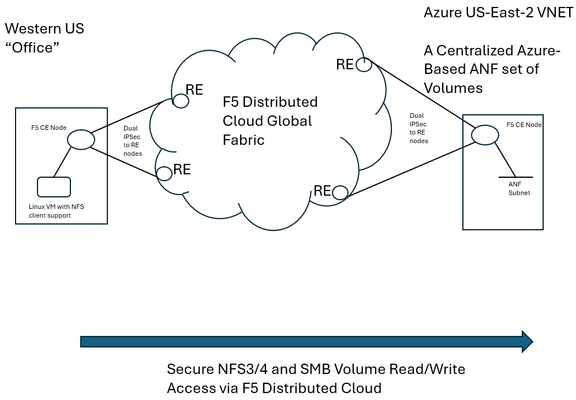
F5 Distributed Cloud (XC) Secure Multicloud Networking (MCN) connects and secures distributed applications across offices, data centers, and various cloud platforms. Frequently the technology is web-based, meaning traffic is often carried on ports like TCP port 443, however other traffic types are also prevalent in an enterprise’s traffic mix. Examples include SSH or relational database protocols. One major component of networked traffic is Network-Attached Storage (NAS), a protocol in the past frequently carried over LANs between employees in offices and co-located NAS appliances, perhaps in wiring closets or server rooms. An example of such an appliance would be the ONTAP family from NetApp which can take on physical or virtual form factors. NAS protocols are particularly useful as they integrate file stores into operating systems such as Microsoft Windows or Linux distributions as directories, mounted for easy access to files at any time, often permanently. This contrasts with SSH file transfers, which are often ephemeral actions and not so tightly integral to host operating system health. With the rise of remote work, often the NAS appliances see increasing file reads-and-writes to these directories, traversing wide-area links. In fact, one study analyzing fundamental traffic changes due to the Covid-19 pandemic saw a 22 percent increase in file transfer protocol (FTP) in a single year, suggesting access to files has undergone significant foundational changes in recent years. Distributed Cloud and the Movement towards Centralized Enterprise Storage A traditional concern about serving NAS files to offices from a centralized point, such as a cloud-instantiated file repository, is latency and reliability. With F5’s Distributed Cloud offering a 12 Tbps aggregate backbone and dedicated RE-to-RE links, the behavior of the network component is both highly durable and performant. The efficiencies of a centralized corporate file distribution point, with the required 9’s of guaranteed uptime of modern cloud services, and the logic of moving towards cloud-served NAS solutions makes a lot of sense. With on-premises storage appliances replaced by a secure, networked service eliminates the need to maintain costly spares, which are effectively a shadow NAS appliance infrastructure and onerous RMA procedures. All of this enables accomplishing the goal of shrinking/greening office wiring closets. To demonstrate this centralized model for a NAS architecture, a configuration was created whereby a west coast simulated office was connected by F5 Distributed Cloud to Azure NetApp Files (ANF) instantiated in Azure East-2 region. ANF is Microsoft Azure’s newest native file serving solution, managed by NetApp, with data throughputs that increase in lock step with the amount of reserved storage pool capacity. Different quality of service (QoS) levels are selectable by the consumer. In the streamlined ANF configuration workflow, where various transaction latency thresholds may be requested, even the most demanding relational database operations are typically accommodated. Microsoft offers additional details on ANF here, however, this article should serve to sufficiently demonstrate the ANF and F5 Distributed Cloud Secure MCN solutions for most readers. Distributed Cloud and Azure NetApp Files Deployment Example NAS in the enterprise today largely involves use of either NFS or SMB protocols, both of which can be used within Windows and Linux environments and make remote directories appear and perform as if local to users. In our example, a western US point of presence was leveraged to serve as the simulated remote office and standard Linux hosts to serve as the consumers of NetApp volumes. In the east, a corporate VNET was deployed in an Azure resource group (RG) in US-East-2, with one subnet delegated to provide Azure NetApp Files (ANF). To securely connect the west coast office to the eastern Azure ANF service, F5 Distributed Cloud Secure MCN was utilized to create a Layer 3 multi-cloud network offering. This is achieved by easily dropping an F5 customer edge (CE) virtual appliance into both the office and the Azure VNET in the east. The CE is a 2-port security appliance. The inside interfaces on both CEs were attached to a global virtual network, and exclusive layer-3 associations to allow simple connectivity and fully preserve privacy. In keeping with the promise of SaaS, Distributed Cloud users require no routing protocol setup. The solution takes care of the control plane, including routing and encryption. This concept could be scaled to hundreds of offices, if equipped with CEs, and easily attached to the same global virtual network. CEs, at boot-up, automatically attach via IP Sec (or SSL) tunnels to geographically close F5 backbone nodes, called regional edge (RE) sites. Like tunnel establishment, routing tables are updated under-the-hood to allow for a turn-key security relationship between Azure NetApp File volumes and consuming offices. The setup is depicted as follows: Setup Azure NetApp Files (ANF) Volumes in Minutes To put the centralized approach to offering NAS volumes for remote offices or locations into practice, a series of quick steps are undertaken, which can all be done through the standard Microsoft Azure portal. The four steps are listed below, with screenshots provided for key points in the brief process: If not starting from an existing Resource Group (RG), create a new RG and add an Azure VNET to it. Delegate one subnet in your VNET to support ANF. Under “Delegate Subnet to a Service” select from the pull-down-list the entry “Microsoft.NetApp/volumes”. Within the Resource Group, choose “Create” and make a NetApp account. This will appear in the Azure Marketplace listings as “Azure NetApp Files”. In your NetApp account, under “Storage service” create a capacity pool. The pool should be sized appropriately, larger is typically better, since numerous volumes, supporting your choice of NFS3/4 and SMB protocols, will be created from this single, large disk pool. Create your first volume, select size, NAS protocols to support, and QoS parameters that meet your business requirements. As seen below, when adding a capacity pool simply follow the numerical sequence to add your pool, with a newly created sample 2 TiB pool highlighted; 1,024 TiB (1 PiB) are possible (click image to enlarge). Interestingly, the capacity pool shown is the “Standard” service level, as opposed to “Premium” and “Ultra”. With QoS type of Auto selected, Azure NetApp Files provides increasing throughput in terms of megabytes per second as the number of TiB in the pool increases. The throughput also increases with service levels; for standard, as shown, 8 megabytes per second per TiB will be allocated. Beyond throughput, ANF also provides the lowest latency averages for reads and writes in the Azure portfolio of storage offerings. As such, ANF is a very good fit for database deployments that must see constrained, average latency for mission-critical transactions. Deeper discussion around ANF service levels may be explored through the Microsoft document here. The next screenshot shows the simple click-through sequence for adding a volume to the capacity pool, simply click on volumes and the “+Add volume” button. A resulting sample volume is displayed in the figure with key parameters highlighted. In the above volume (“f5-distributed-cloud-vol-001”) the NAS protocol selected was NFSv3 and the size of the volume (“Quota”) was set to 100GiB. Setup F5 Distributed Cloud Office-to-Azure Connectivity To access the volume in a secured and highly responsive manner, from corporate headquarters, remote offices or existing data centers, three items from F5 Distributed Cloud are required: A customer edge (CE) node, normally with 2-ports, must be deployed in the Azure RG VNET. This establishes the Azure instance as a “site” within the Distributed Cloud dashboard. Hub and spoke architectures may also be used if required, where VNET peering can also allow the secure multi-cloud network (MCN) solution to operate seamlessly. A CE is deployed at a remote office or datacenter, where file storage services are required by various lines of business. The CE is frequently deployed as a virtual appliance or installed on a bare metal server and typically has 2-ports. To instantiate a layer-3 MCN service, the inside ports of the two CEs are “joined” to a virtual global network created by the enterprise in the Distributed Cloud console, although REST API and Terraform are also deployment options. By having each inside port of the Azure and office CE’s joined to the same virtual network, the “inside” subnets can now communicate with each other, securely, with traffic normally exchanged over encrypted high-speed IPSec tunnels into the F5 XC global fabric. The following screenshot demonstrates adding the Azure CE inside interface to a global virtual network, allowing MCN connectivity to remote office clients requiring access to volumes. Further restrictions, to prevent unauthorized clients, are found within NAS protocols themselves, such as simple Export policies in NFS and ACL rules in SMB/CIFS, which can be configured quickly within ANF. Remote Office Access – Establish Read/Write File Access to Azure ANF over F5 Distributed Cloud With both ANF configured and F5 Distributed Cloud now providing a layer-3 muticloud network (MCN) solution, to patch enterprise offices to the centralized storage, some confirmation of the solution working as expected was desired. First off, a choice in protocols was made. When configuring ANF, the normal choices for access are NFSv3/v4 or SMB/CIFS or both protocols concurrently. Historically, Microsoft hosts made use of SMB/CIFS and Linux/Unix hosts preferred NFS, however today both protocols are used throughout enterprises. One example being long-time SAMBA server (SMB/CIFS) support in the world of Linux. Azure NetApp Files will provide all the necessary command samples to get hosts connected without difficulty. For instance, to mount the volume to a folder off the Linux user home directory, such as the sample folder “f5-distributed-cloud-vol-001”, per the ANF suggestion the following one command will connect the office Linux host to the central storage in Azure-East-2: sudo mount -t nfs -o rw,hard,rsize=262144,wsize=262144,vers=3,tcp 10.0.9.4:/f5-distributed-cloud-vol-001 f5-distributed-cloud-vol-001 At this point the volume is available for day-to-day tasks, including read and write operations, as if the NAS solution were local to the office, often literally down the hallway. Remote Office Access - Demonstration of Azure ANF over F5 Distributed Cloud i zThe following sample wrote a file of 20,000 bytes to the ANF service, waited a few seconds, and then removed the file before beginning another cycle. At the lowest common denominator, packet analysis for the ensuing traffic from the western US office will indicate both network and application latency sample values. As depicted in the following Wireshark trace, the TCP response to a transmitted segment carrying an NFS command, was observed to be just 74.5 milliseconds. This prompt round-trip latency for a cross-continent data plane suggests a performant Distributed Cloud MCN service level. This is easily seen as the offset from the reference timestamp (time equal to zero) of the NFS v3 Create Call. Click on image to expand. Analyzing the NAS response from ANF (packet 185) arrives less than 1 millisecond later, suggesting a very responsive, well-tuned NFS control plane offered by ANF. To measure the actual, write-time of a file from west coast to east coast, the following trace demonstrates the 20,000 byte file write exercise from the shell script. In this case, the TCP segments making up the file, specifically the large packet body lengths called out in the screenshot, are delivered efficiently without TCP retransmissions, TCP zero window events, nor having any indicators of layer 3 and 4 health concerns. The entirety of the write is measured at the packet layer to take only 150.8 milliseconds. Since packet-level analysis is not the most turnkey, easy method to monitor file read and write performance, a set of Linux and Windows utilities can also be leveraged. The Linux utility nfsiostat was concurrently used with the test file writes and produced similar, good latency measurements. Nfsiostat monitoring of the file write testing, from west coast to east coast, for the 20,000-byte file, has indicated an average write time to ANF of 151 milliseconds. The measurements presented here are simply observational, to present rapid, digestible techniques for readers interested in service assurance for running ANF over an XC L3 MCN offering. For more rigorous monitoring treatments, Microsoft provides guidance on performing one’s own measurements of Azure NetApp Files here. Summary As enterprise-class customers continue to rapidly look towards cloud for compute performance, GPU access, and economies-of-scale savings for key workloads, the benefits of a centralized, scalable storage counterpart to this story exists. F5 Distributed Cloud offers the reach and performance levels to securely tie existing offices and data centers to cloud-native storage solutions. One example of this approach to modernize storage was covered in this article, the turn-key ability to begin transitioning from traditionally on-premises NAS appliances to cloud-native scalable volumes. The Azure NetApp Files approach to serving read/write volumes allows modern hosts, including Windows and Linux distributions, to utilize virtually unlimited folder sizes with service levels adjustable to business needs.70Views0likes1CommentF5 Distributed Cloud – Multiple custom certificates for HTTP/TCP LB
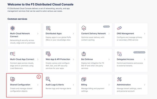
TLS Certificate A TLS certificate is a digital certificate signed by a trusted Certificate Authority (CA) that will authenticate the identity of the certificate owner. It is required to encrypt and secure traffic over the internet using Public Key Infrastructure (PKI). F5 Distributed Cloud (F5 XC) had already implemented the ability to choose between automatic TLS certificate management and attaching a custom TLS certificate (aka Bring Your Own Certificate) in its HTTP/TCP load balancer configurations. Now a new feature is added enabling customers to attach multiple custom TLS certificates to a single HTTP/TCP load balancer, this will allow them to host multiple domains with different certificates from a single load balancer so that they can optimize costs or simplify configuration. Also, now TLS certificates can be shared across multiple LBs and customers can view and manage their TLS certificates and intermediate certificate chains as standalone objects from a centralized place. Note: This feature is supported for the HTTP/TCP LBs advertised either on Regional Edges (REs) or on Customer Edge (CE). Configuration Step1: Create TLS certificate object in XC console Select `Shared Configuration` service from the home page of XC console. Select `Certificate Management` from the left menu and select `TLS Certificates`, Click `Add TLS Certificate`. Note: Certificate Management configuration can be done either from Multi-Cloud App Connect, Web App & API Protection, Distributed Apps, or Shared Configuration services. Configure certificate properties and upload the certificate. Note: Supported certificate formats are PEM and PKCS#12 (aka P12) Optionally, configure OCSP stapling and intermediate certificate chain. OCSP (Online Certificate Status Protocol) is used to determine the revocation state of digital certificates. For more information on OCSP stapling follow the documentation Certificate Chain of trust refers to all the certificates that are linked together in an ordered fashion to validate the legitimacy of the server certificate. There are 3 components in this certificate chain: Root certificate: This certificate belongs to Root Certificate Authority (CA) and are self-signed. Intermediate certificate: This certificate belongs to intermediate CA and are signed by Root CA, Intermediate CA signs the certificates on behalf of Root CA and there can be one or more Intermediate CA in a certificate chain of trust. Leaf/server certificate: This certificate belongs to the web server to establish secure connection or authenticating clients reaching to the server, this can either be signed by a Root CA or an Intermediate CA. Above screenshot shows the list of TLS Certificates, one certificate is signed by the Root CA and is created in personal namespace (demo) while the other certificate is signed by the Intermediate CA and is created in `shared namespace` (Note: objects created in shared namespace can be used across all other namespaces). Step2: Attach TLS certificates to the load balancer (HTTP/TCP) Note: In this demonstration, we are attaching the TLS certificates to the HTTP LB Click on `Load Balancers`, from the left menu and select `HTTP Load Balancers`. Click Add `HTTP Load Balancer`, Configure HTTP LB, enter valid domains as per the TLS certificates. Select ‘HTTPS with Custom Certificate’ option in ‘Load Balancer Type’ field, and in ‘TLS Configuration’ select `Multiple Certificates` option. Click on ‘Configure’ and attach the above created TLS certificates by keeping ‘TLS Security Level’ as `High`. We have already created origin pools for our two domains and added those origin pool members to the LB with the help of ‘Routes’ as shown inthe screenshots below. (Applications deployed on origin servers are httpbin and dvga) You could either advertise this LB to the internet which is also a default setting or can customize it to be advertised on a CE site. For this demo we have advertised the LB to 'Internet'. Click `Save and Exit`. Note:Each LB has a certificate expiration date, and in case of multiple certs this value is automatically set to the expiry date of its certificate which is expiring earlier. Similarly, you can configure TCP LB as well with multiple custom TLS certificates. For more details on how to configure TCP LB refer to the document. Step3: Check the server certificate details by clicking padlock next to the URL Open the browser and check for the LB domains, Connection should be shown as secure. Note: In this demo we are using local domain names and TLS Certificates, so we have manually added the custom local `Root CA` certificate to the browser and edited the hosts file to map VIP with our domain names. When the certificate expiry date approaches near, you will be notified with alerts. You can see active alerts by navigating to `Notifications -> Alerts` section from the menu on the left side or by clicking the bell icon on top right corner of the XC console. Based on the alerts received, you can renew the certificate expiration date and upload it again to the existing XC’s TLS cert object to reuse it instead of creating a new object. Conclusion: In the above demo, you have seen using XC console how easy it is to manage your multiple custom TLS certificates from a centralized place.2.8KViews3likes0CommentsDeploy WAF on any Edge with F5 Distributed Cloud (SaaS Console, Automation)
F5 XC WAAP/WAF presents a clear advantage over classical WAAP/WAFs in that it can be deployed on a variety of environments without loss of functionality. In this first article of a series, we present an overview of the main deployment options for XC WAAP while follow-on articles will dive deeper into the details of the deployment procedures.5.3KViews9likes0CommentsThe App Delivery Fabric with Secure Multicloud Networking
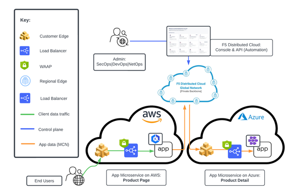
This tutorial with accompanying workflow guide deploys customer edge sites and uses Distributed Cloud Multicloud Networking App Connect to establish a Secure MCN App Delivery Fabric, enabling only Layer7 app connectivity between two cloud sites. Manual and automation workflows show how to make this NetOps and DevOps task come to life.152Views1like0CommentsSecure RAG for Safe AI Deployments Using F5 Distributed Cloud and NetApp ONTAP
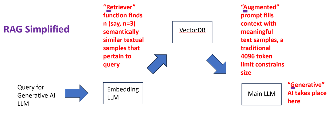
Retrieval Augmented Generation (RAG) is one of the most discussed techniques to empower Large Language Models (LLM) to deliver niche, hyper-focused responses pertaining to specialized, sometimes proprietary, bodies of knowledge documents. Two simple examples might include highly detailed company-specific information distilled from years of financial internal reporting from financial controllers or helpdesk type queries with the LLM harvesting only relevant knowledge base (KB) articles, releases notes, and private engineering documents nor normally exposed in their entirety. RAG is highly bantered about in numerous good articles; the two principal values are: LLM responses to prompts (queries) based upon specific, niche knowledge as opposed to the general, vast pre-training generic LLMs are taught with; in fact, it is common to instruct LLMs not to answer specifically with any pre-trained knowledge. Only the content “augmenting” the prompt. Attribution is a key deliverable with RAG. Generally LLM pre-trained knowledge inquiries are difficult to traceback to a root source of truth. Prompts augmented with specific assistive knowledge normally solicit responses that clearly call out the source of the answers provided. Why is the Security of RAG Source Content Particularly Important? To maximize the efficacy of LLM solutions in the realm of artificial intelligence (AI) an often-repeated adage is “garbage in, garbage out” which succinctly states an obvious fact with RAG: valuable and actionable items must be entered into the model to expect valuable, tactical outcomes. This means exposing key forms of data, examples being data which might include patented knowledge, intellectual property not to be exposed in raw form to competitors. Actual trade secrets, which will infuse the LLM but need to remain confidential in their native form. In one example around trade secrets, the Government of Canada spells out a series of items courts will look at in determining compensation for misuse (theft) of intellectual property. It is notable that the first item listed is not the cost associated with creation of the secret material (“the cost in money or time of creating or developing the information”) but rather the very first item is instead how much effort was made to keep the content secure (“the measures taken to maintain secrecy”). With RAG, incoming queries are augmented with rich, semantically similar enterprise content. The content has already been populated into a vector database by converting documents, they might be pdf or docx as examples, into raw text form and converting chunks of text into vectors. The vectors are long sequences of numbers with similar mathematical attributes for similar content. As a trivial example, one-word chunks such as glass, cup, bucket, jar might be semantically related, meaning similarities can be construed by both human minds and LLMs. On the other hand, empathy, joy, and thoughtfulness maintain similarities of their own. This semantic approach means a phrase/sentence/paragraph (chunk) using bow to mean “to bend in respect” as opposed to the “front end of a ship” or “something to tie one’s hair back with”, even a tool every violinist would need. The list goes on; all semantic meanings of bow are very different in these chunks and would have distinctive embeddings within a vector database. The word embedding is likely derived from “fixing” or “planting” an object. In this case, words are “embedded” into a contextual understanding. The typical length of the number sequence describing the meaning of items has typically been more than 700, but this number of “dimensions” applied is always a matter of research, and the entire vector database is arrived at with an embedding LLM, distinct from the main LLM that will produce generative AI responses to our queries. Incoming queries destined for the main generative AI LLM can, in turn, be converted to vectors themselves by the very same text-embedding “helper” LLM and through retrieval (the “R” in RAG) similar textual content can buttress the prompt presented to the main LLM (double click to expand). Since a critical cog in the wheel of the RAG architecture is the ingestion of valuable and sensitive source documents into the vector database, using the embedding LLM, it is not just prudent but critical that this source content be brought securely over networks to the embedding engine. F5 Distributed Cloud Secure Multi-cloud Networking and NetApp ONTAP For many practical, time-to-market reasons, modern LLMs, both the main and embedding instances, may not be collocated with the data vaults of modern enterprises. LLMs benefit from cloud compute and GPU access, something often in short supply for on-premises production roll outs. A typical approach assisted by the economies of scale might be to harvest public cloud providers, such as Azure, AWS, and Google Cloud Platform for the compute side of AI projects. Azure, as one example, can turn up virtual machines with GPUs from NVIDIA like A100, A2, and Tesla T4 to name a few. The documents needed to feed an effective RAG solution may well be on-premises, and this is unlikely to change for reasons including governance, regulatory, and the weight of decades of sound security practice. One of the leading on-premises storage solutions of the last 25 years is the NetApp ONTAP storage appliance family, and reflected in this quote from NVIDIA: "Nearly half of the files in the world are stored on-prem on NetApp." — Jensen Huang, CEO of NVIDIA A key deliverable of F5 Distributed Cloud is providing encrypted interconnectivity of disparate physical sites and heterogeneous cloud instances such as Azure VNETs or AWS VPCs. As such, there are two immediate, concurrent F5 features that come to mind: Secure interconnectivity of on-premises NetApp volumes (NAS) or LUNs (Block) containing critical documents for ingestion into RAG. Utilize encrypted L3 connectivity between the enterprise location and the cloud instance where the LLM/RAG are instantiated. TCP load balancers are another alternative for volume sharing NAS protocols like NFS or SMB/CIFS. Secure access to the LLM web interface or RESTful API end points, with HTTPS load balancers including key features like WAF, anti-bot mechanisms, and API automatic rate limiting for abusive prompt sources. The following diagram presents the topology this article set out to create, RE are “regional edge” sites maintained internationally by F5 and harness private RE to RE, high-speed global communication links. DNS names, such as the target name of an LLM service, will leverage mappings to anycast IP addresses, thus users entering the RE network from southeast Asian might, for example, enter the Singapore RE while users in Switzerland might enter via a Paris or Frankfurt RE. Complementing the REs are Customer Edge (CE) nodes. There are virtual or physical appliances which act as security demarcation points. For instance, a CE placed in an Azure VNET can protect access to the server supporting the LLM, removing any need for Internet access to the server, which is now entirely accessible only through a private RFC-1918 type of private address. External access to the LLM for just employees or, maybe employees and contractors, or potentially access for the Internet community is enabled by a distributed HTTPS load balancer. In the example depicted above, oriented towards full Internet access, the FQDN of the LLM is projected by the load balancer into the global DNS and consumers of the service resolve the name to one IP address and are attracted to the closest RE by BGP-4’s support for anycast. As the name “distributed” load balancer suggests, the origin pool can be in an entirely different site than the incoming RE, in this case the origin pool is the LLM behind the CE in the Azure VNET. The LLM requests travel from RE to CE via a highspeed networking underlay. The portion of the solution that securely ties the LLM to the source content required for RAG to embed vectors, is in this case, utilizing layer 3 multi-cloud networking (MCN). The solution is turnkey, routing table are automatically connected to members of the L3 MCN, in this case the inside interfaces of the Azure CE and Redmond, Washington on-premises CE and traffic flows over an encrypted underlay network. As such, the NetApp ONTAP cluster can securely expose volumes with key file ware via a protocol like Network File System (NFS), no risk of data exposure to third-party prying eyes exists. The following diagram drills into the RE and CE and NetApp interplay (double click to expand). F5 Distributed Cloud App Connect and LLM Setup This article speaks to hands-on experience with web-driven LLM inferencing with augmented prompts derived from a RAG implementation. The AI compute was instantiated on an Azure-hosted Ubuntu 20.04 virtual machine with 4 virtual cores. Installed software included Python 3.10, and libraries such as Langchain, Pypdf (for converting pdf documents to text), FAISS (for similarity searching via a vector database), and other libraries. The actual open source LLM utilized for the generative AI is found here on huggingface.co. The binary exceeds 4 GB however, is considered effective for CPU-based deployments. The embedding LLM model, critical to seed the vector database with entries derived from secured enterprise documentation, and then used again per incoming query for RAG similarity searches to build augmented prompts, was from Hugging Face: sentence-transformers/all-MiniLM-L6-v2 and can be found here. The AI RAG solution was implemented in Python3, and as such the Azure Ubuntu can be accessed both by SSH or via Jupyter Notebooks. The latter was utilized as this is the preferred final delivery mechanism for standard users, not a web chatbot design or the requirement to use API commands through solutions like Postman or Curl. This design choice, to steer the user experience towards Jupyter Notebook consumption, is in keeping with the fact that it has become a standard in AI LLM usage where the LLM is tactical and vital to an enterprise's lines of business (LOBs). Jupyter Notebooks are web-accessed with a browser like Chrome or Edge and as such, F5’s WAF, anti-bot, and L7 DDoS, all part of the F5 WAAP offering, can easily be laid upon an HTTP load balancer with a few mouse clicks in XC to provide premium security to the user experience. NetApp and F5 Distributed Cloud Secure Multi-cloud Networking The secure access to files for ingestion into the vector database, for similarity searches when user queries are received, makes use of an encrypted L3 Multi-cloud Network relationship between the Azure VNET and the LAN on prem in Redmond, Washington hosting the NetApp ONTAP cluster. The specific protocol chosen was NFS and the simplicity is demonstrated by the use of one Linux command to present key, high-valued documents for the AI steps to populate the database: #mount -t nfs <IP Address of NetAPP LIF interface on-prem>:/Secure_docs_for_RAG /home/ubuntu_restriced_user/rag_project/docs/Secure_docs_for_RAG. This address is available nowhere else in the world except behind this F5 CE in the Azure VNET. After the pdf files are converted to text, chunked to reasonable sizes with some overlap suggested between the end of one chunk and the start of the next chunk, the embedding LLM will populate the vector database. The files are always only accessed remotely by NFS through the mounted volume, and this mount may be terminated until new documents are ready to be added to the solution. The Objective RAG Implementation - Described In order to have a reasonable facsimile of the real-word use cases this solution will empower today, but not having any sensitive documents to be injected, it was decided to use some seminal “Internet Boom”-era IETF Requests for Comment (RFCs) as source content. With the rise of multi-port routing and switching devices, it became apparent the industry badly needed specific and highly precise definitions around network device (router and switch) performance benchmarking to allow purchasers “apples-to-apples” comparisons. These documents recommend testing parameters, such as what frame or packet sizes to test with, test iteration time lengths, when to use FIFO vs LIFO vs LILO definitions of latency, etc. RFC-1242 (Request for Comment, terminology) and RFC-2544 (methodologies), chaired by Scott Bradner of Harvard University, and the later RFC 2285 (LAN switching terminologies), chaired by Bob Mandeville then of European Network Laboratories are three prominent examples, to which test and measurement solutions aspired to be compliant. Detailed LLM answers for quality assurance engineers in the network equipment manufacturing (NEM) space is the intended use case of the design, answers that must be distilled specifically by generative AI considering queries augmented by RAG and specifically only based upon these industry-approved documents. These documents are, of course, not containing trade secrets or patented engineering designs. They are in fact publicly available from the IETF, however they are nicely representative of the value offered in sensitive environments. Validating RAG – Watching the Context Provided to the LLM To ensure RAG was working, the content being augmented in the prompt was displayed to screen, we would expect to see relevant clauses and sentences from the RFCs being provided to the generative AI LLM. Also, if we were to start by asking questions that were outside the purview of this testing/benchmarking topic, we should see the LLM struggle to provide users a meaningful answer. To achieve this, rather than, say, asking what 802.3/Ethernetv2 frame sizes should be used in throughput measurements, and what precisely is the industry standard definition of the term “throughput” was, the question instead pertained to a recent Netflix release, featuring Lindsay Lohan. Due to the recency of the film, even if the LLM leaned upon its pretrained model, it will come up with nothing meaningful. “Question: Important, only use information provided as context in the prompt, do not use other trained knowledge. Please identify who played Heather in the March 2024 Lindsay Lohan Netflix movie titled Irish Wish?” As seen in the following Jupyter screenshot, the RAG solution can only provide augmented prompts from the database, in this case it has some test and measurement clauses and some rules pertaining to the winter ice sport of curling (double click to enlarge). The supportive context data augmenting the prompt was, as expected, not going to help in this off-the-wall query, as only the RFCs and some sports rules had been introduced to the vector database. What is especially noteworthy is the LLM did not simply admit it could not possibly answer this question but hallucinated a very articulate response that indicated “Heather played for her team against Lindsay Lohan’s Team Ireland”. To validate the RAG architecture for a working scenario, actually pertinent to the movie, a film review in pdf format was added to the ONTAP cluster-housed volume. The supportive documentation was consumed (using Pypdf from the Jupyter Notebook it became text). It was automatically chunked and introduced to the FAISS vector database through the Hugging Face embedding LLM. With the RAG vector database populated by the embedding LLM, the responses then became meaningful. The following exchange shows the value of RAG in producing meaningful, thought-out answers: Question: Important, only use information provided as context in the prompt, do not use other pre-trained knowledge. Who does Maddie edit novels for in the Lindsay Lohan March 2024 Netflix movie titled Irish Wish? Answer: Let's think step by step. We know that Maddie Kelly plays a book editor who harbors a big secret, and we have been given information about her job as an editor for Paul Kennedy (played by Alexander Vlahos), which is also part of the question context provided above. Therefore it seems logical to infer that she edits novels in general but specifically those written or co-written by author Paul Kennedy - who happens to be a bestselling romance novelist as stated earlier on, so we can safely conclude Maddie works for Paul himself (as opposed to any other book publishing company). This time we see relevant, meaningful context provided by RAG, with relevant portions of the pdf file review document augmenting the prompt. The augmentations are normally not displayed unless requested by the user or programmer, unlike humans, LLMs do not require superfluous text formatting (advantage: LLMs) and thus the content is packed tightly and efficiently. Fewer characters also mean fewer tokens get used by the targeted AI model and can allow more data before a token context limit is reached. In pay-for-use LLM approaches fewer tokens also help the enterprise’s bottom line financially. Also, note that the answer will likely not always be identical with subsequent asks of the same question as per LLM normal behavior. Features like “temperature setting” can also allow more “creative” ideas in responses, injecting humor and even outlandishness if desired. The RAG workflow is now validated, but the LLMs in question (embedding and main generative LLM) can still be made better with these suggestions: Increase “chunk” sizes so ideas are not lost when excessive breaks make for short chunks. Increase “overlap” so an idea/concept is not lost at the demarcation point of two chunks. Most importantly, provide more context from the vector database as context lengths (maximum tokens in a request/response) are generally increasing in size. Llama2, for instance, typically has a 4,096 context length but can now be used with larger values, such as 32,768. This article used only 3 augmentations to the user query, better results could be attained by increasing this value at a potential cost of more CPU cycles. Using Secure RAG – F5 L3 MCN, HTTPS Load Balancers and NetApp ONTAP Together With the RAG architecture validated to be working, the solution was used to assist the target user entering queries to the Azure server by means of Jupyter Notebooks, with RAG documents ingested over encrypted, private networking to the on-premises ONTAP cluster NFS volumes. The questions posed, which are answerable by reading and understanding key portions spread throughout the Scott Bradner RFCs, was: “Important, only use information provided as context in the prompt, do not use other pre-trained knowledge. Please explain the specific definition of throughput? What 802.3 frame sizes should be used for benchmarking? How long should each test iteration last? If you cannot answer the questions exclusively with the details included in the prompt, simply say you are unable to answer the question accurately. Thank you." The Jupyter Notebook representation of this query, which is made in the Python language and issued from the user’s local browser anywhere in the world and directly against the Azure-hosted LLM, looks like the following (click to expand image): The next screenshot demonstrates the result, based upon the provided secure documents (double click to expand). The response is decent, however, the fact that it is clearly using the provided augmentations to the prompt, that is the key objective of this article. The accuracy of the response can be questionable in some areas, the Bradner RFCs highlighted the importance of 64-byte 802.3/Ethernetv2 frame sizes in testing, as line rate forwarding with this minimum size produces the highest theoretically possible frame per second load. In the era of software driven forwarding in switches and routers this was very demanding. Sixty-four byte frames result in 14,881 fps (frames per second) for 10BaseT, 148,809 fps for 100BaseT, 1.48 million fps for Gigabit Ethernet. These values were frequently more aspirational in earlier times and also a frequent metric used in network equipment purchasing cycles. Suspiciously, the LLM response calls out 64kB in 802.3 testing, not 64B, something which seems to be an error. Again, with this architecture, the actual LLM providing the generative AI responses is increasingly viewed as a commodity, alternative LLMs can be plugged quickly and easily into the RAG approach of this Jupyter Notebook. The end user, and thus the enterprise itself, is empowered to utilize both different LLMs, purchased or open-source from sites like Hugging Face, to determine optimal results. The other key change that can affect the overall accuracy of results is to experiment with different embedding models. In fact, there are on-line “leader” boards strictly for embedding LLMs so one can quickly swap in and out various popular embedding LLMs to see the impact on results. Summary and Conclusions on F5 and NetApp as Enablers for Secure RAG This article demonstrated an approach to AI usage that leveraged the compute and GPU availability that can be found today within cloud providers such as Azure. To safely access such an AI platform for a production-grade enterprise requirement, F5 Distributed Cloud (XC) provided HTTPS load balancers to connect worker browsers to a Jupyter Notebook service on the AI platform, this service applies advanced security upon the traffic within the XC, from WAF to anti-bot to L3/L7 DDOS protections. Utilizing secure Multi-cloud Networking (MCN), F5 provided a private L3 connectivity service between the inside interface on an Azure VNET-based CE (customer edge) node and the inside interface of an on-premises CE node in a building in Redmond, Washington. This secure network facilitated a NFS remote volume, content on spindles/flash in on-premises NetApp ONTAP to be remotely mounted on the Azure server. This secure file access provided peace of mind to exposing potentially critical and private materials from NetApp ONTAP volumes to the AI offering. RAG was configured and files were ingested, populating a vector database within the Azure server, that allowed details, ideas, and recommendations to be harnessed by a generative AI LLM by augmenting user prompts with text gleaned from the vector database. Simple examples were used to first demonstrate that RAG was working by posing queries that should not have been addressed by the loaded secure content; such a query was not suitably answered as expected. The feeding of meaningful content from ONTAP was then demonstrated to unleash the potential of AI to address queries based upon meaningful .pdf files. Opportunities to improve results by swapping in and out the main generative AI model, as well as the embedding model, were also considered.353Views1like0CommentsDeploy Bot Defense on any Edge with F5 Distributed Cloud (SaaS Console, Automation)
Introduction This guide, along with the provided scripts and sample app and services, is designed to help explore and demonstrate the use cases of the F5 Distributed Cloud (XC) Bot Defense in a variety of different cloud environments including AWS, Azure, GCP, and within the Distributed Cloud (XC) Regional Edge. XC Bot Defense Connector Strategy F5 Distributed Cloud Bot Defensemeets you where you’re at when it comes to deployment flexibility.We make it ridiculously easy for you to deploy XC Bot Defense either in the cloud, on-prem, or as a hybrid configuration with pre-built connecters in leading application platforms and CDNs to make deployment easy and fast. Choose Your Path Within each deployment scenario, you can choose your path with the following options to deploy the specified Bot Defense environment using either the console deployment link or automation with terraform. Module 1 Deploy Bot Defense on Regional Edges with F5 Distributed Cloud Module 2 Deploy F5 XC Bot Defense for AWS Cloudfront with F5 Distributed Cloud Module 3 Deploy Bot Defense in Azure with BIG-IP Connector for F5 Distributed Cloud Module 4 Deploy Bot Defense in GCP Using BIG-IP Connector for F5 Distributed Cloud XC Bot Defense Scenarios The modules below lay out a framework for connecting and managingdistributed app services for this scenario, with a focus on the three core use cases. MODULE 1: Deploy Bot Defense on Regional Edges with F5 Distributed Cloud In this scenario, we will be deploying our fictitious airline application into a Regional Edge location of our choosing via the VK8's service in XC. We'll walk through all of the required steps, provide the vk8's manifest file and front end this application with an XC HTTP Load Balancer. In addition, the HTTP Load Balancer will be used to front-end our application and enable our XC Bot Defense Service. Choose your path: Console Steps for XC Bot Defense on Regional Edges Coming Soon*** Automated Deployment of XC Bot Defense on Regional Edge via Terraform MODULE 2:Deploy F5 XC Bot Defense for AWS Cloudfront with F5 Distributed Cloud In this scenario, we will be deploying our fictitious application in AWS with the XC Bot Defense Connector for AWS Cloudfront Distributions. Choose your path: Console Steps to Deploy F5 XC Bot Defense for AWS Cloudfront Coming Soon*** Automated Deployment of XC Bot Defense for AWS Cloudfront MODULE 3: Deploy Bot Defense in Azure with BIG-IP Connector for F5 Distributed Cloud In this scenario, we will be deploying our fictitious application into Azure with the XC Bot Defense Connector for BIG-IP. Choose your path: Console Steps to Deploy F5 XC Bot Defense in Azure with BIG-IP Connector Coming Soon*** Automated Deployment of XC Bot Defense in Azure with BIG-IP Connector MODULE 4: Deploy Bot Defense in GCP Using BIG-IP Connector for F5 Distributed Cloud In this scenario, we will be deploying our fictitious application into GCP with the XC Bot Defense Connector for BIG-IP. Choose your path: Console Steps to Deploy F5 XC Bot Defense in GCP Using BIG-IP Connector Coming Soon*** Automated Deployment of XC Bot Defense in GCP with BIG-IP Connector For additional information, refer to these resources: Deploy Bot Defense on any Edge with F5 Distributed Cloud (SaaS Console, Automation) GitHub repository with the walk-throughof the deployment steps & demo YouTube video seriesdiscussing the different aspects of this configuration DevCentral Learning Series: Edge Compute Get Started with F5 Distributed Cloud Services482Views4likes2CommentsMaking Mobile SDK Integration Ridiculously Easy with F5 XC Mobile SDK Integrator
Introduction To prevent attackers from exploiting mobile apps to launch bots, F5 provides customers with the F5 Distributed Cloud (XC) Mobile SDK, which collects signals for the detection of bots. To gain this protection, the SDK must be integrated into mobile apps, a process F5 explains in clear step-by-step technical documentation. Now, F5 provides an even easier option, the F5 Distributed Cloud Mobile SDK Integrator, a console app that performs the integration directly into app binaries without any need for coding, which means no need for programmer resources, no need to integration delays. The Mobile SDK Integrator supports most iOS and Android native apps. As a console application, it can be tied directly into CI/CD pipelines to support rapid deployments. Use Cases While motivations for using SDK Integrator may vary, below are some of the more common reasons: Emergency integrations can be accomplished quickly and correctly. Customers experiencing active bot attacks may need to integrate with F5 Distributed Cloud Bot Defense immediately and minimize integration risks. Apps using 3rd-party libraries may not be suitable for manual integration, particularly when these libraries do not provide APIs for adding HTTP headers into network requests. In such cases, the SDK Integrator can inject SDK calls into the underlying network stack, bypassing the limitations of the network library. Customers who own multiple apps, which may have different architectures, or are managed by different owners, need a single integration method, one which works for all app architectures and is simple to roll out to multiple teams. The SDK Integrator facilitates a universal integration approach. How It Works The work of the SDK Integrator is done through two commands: the first command creates a configuration profile for the SDK injection, and the second performs the injection. Step 1: $ python3 ./create_config.py --target-os Android --apiguard-config ./base_configuration_android.json --url-filter "*.domain.com/*/login" --enable-logs --outfile my_app_android_profile.dat In Step 1, apiguard-config lets the user specify the base configuration to be used in integration. With url-filter we specify the pattern for URLs which require Bot Defense protection, enable-logs allows for APIGuard logs to be seen in the console, outfile specifies the name of this integration profile. Step 2: $ java -jar SDK-Integrator.jar --plugin F5-XC-Mobile-SDK-Integrator-Android-plugin-4.1.1-4.dat --plugin my_app_android_profile.dat ./input_app.apk --output ./output_app.apk --keystore ~/my-key.keystore --keyname mykeyname --keypass xyz123 --storepass xyz123 In Step 2, we specify which SDK Integrator plugin and configuration profile should be used. In the same step, we can optionally pass parameters for app-signing: keystore, keyname, keypass and storepass. Output parameter specifies the resulting file name. The resulting .apk or .aab file is a fully integrated app, which can be tested and released. Injection steps for iOS are similar. The commands are described in greater detail in the SDK Integrator user guides distributed with the SDK Integrator. Mobile SDK Integrator Video In Conclusion In order to thwart potential attackers from capitalizing on mobile apps to initiate automated bots, The F5 Distributed Cloud Mobile SDK Integrator seamlessly incorporates the SDK into app binaries, completely bypassing the necessity for coding making the process easy and fast. Related Content Deploy Bot Defense on any Edge with F5 Distributed Cloud (SaaS Console, Automation) Protecting Your Native Mobile Apps with F5 XC Mobile App Shield Bot Defense for Mobile Apps in XC WAAP Part 1: The Bot Defense Mobile SDK1.2KViews3likes1CommentProtecting Your Native Mobile Apps with F5 XC Mobile App Shield
Introduction Mobile App Shield is a security technology that integrates directly into mobile applications to provide proactive security against a wide range of attacks, such as tampering, debugging, code injection, code modification and stealing of data from the app. Mobile App Shield is delivered in separate packages for iOS and for Android. Shielding an app with Mobile App Shield is an automated process. Key Capabilities F5 Distribtued Cloud (XC) Mobile App Shield contains multiple security features to counter threats found in the Android and iOS eco-system, and are outlined further below. Product Demo In this Product Demonstration we'll be showcasing Mobile App SHIELD with a product demonstration of how to both integrate SHIELD while also highlighting the protection it provides Conclusion Mobile App Shield represents an advanced security technology seamlessly embedded within mobile applications, offering proactive protection against a diverse array of threats and is easily coupled with XC Bot Defense for comprehensive Mobile App Protection for both Android and iOS. Related Content Deploy Bot Defense on any Edge with F5 Distributed Cloud (SaaS Console, Automation) Bot Defense for Mobile Apps in XC WAAP Part 1: The Bot Defense Mobile SDK F5 Bot Defense Solutions F5 Fraud Solutions F5 Authentication Intelligence The OWASP Automated Threats Project OWASP Automated Threats - CAPTCHA Defeat (OAT-009) OWASP Automated Threats - Credential Stuffing (OAT-008) OWASP Automated Threats - OAT-001 Carding Operationlizing Online Fraud Detection, Prevention, and Response JavaScript Supply Chains, Magecart, and F5 XC Client-Side Defense (Demo) How Attacks Evolve From Bots to Fraud Part: 1 How Attacks Evolve From Bots to Fraud Part: 2 F5 Distributed Cloud Bot Defense (Overview and Demo)2.5KViews4likes2CommentsEnabling F5 Distributed Cloud Client-Side Defense in BIG-IP 17.1
Introduction In the freshest BIG-IP release, version 17.1, we continue to expand, enrich, and streamline the realm of application security, delivery, and automation that BIG-IP platforms provide for applications.In this article we'll be zooming in on the new Distributed Cloud Client-Side Defense connectivity which enables a self-managed service that seamlessly integrates with F5 BIG-IP to protect against client-side attacks such as Magecart, digital skimming, formjacking, (PII) harvesting, and other types of browser-based supply chain attacks. New BIG-IP Distributed Cloud Services Module Immersed within this cutting-edge release we're empowering our customers with an ingenious Distributed Cloud Services Integration Module. This powerful module grants customers the ability to harness their existing BIG-IP deployments and effortlessly apply cloud-based security services to their application transactions, all from within the intuitive BIG-IP console. These remarkable security services act as a catalyst, empowering application owners and security personnel to harness the sheer might of industry-leading Bot and Fraud cloud connectors. This union allows for a seamless integration with the F5 Distributed Cloud Services, ensuring that simplicity and security are bestowed upon every aspect of this integration. XC Client-Side Defense Solution Overview In BIG-IP 17.1 Distributed Cloud Client-Side Defense connectivity enables a self-managed service that seamlessly integrates with F5 BIG-IP to protect against client-side attacks such as Magecart, digital skimming, formjacking, (PII) harvesting, and other types of browser-based supply chain attacks. By providing real-time monitoring of a web application’sJavaScript libraries for malicious activities, Distributed Cloud Client-Side Defense protects consumer data from being accessed by cybercriminals and assists organizations in meeting the new PCI DSS 4.0 requirements CSD Onboarding Demo Conclusion In conclusion, this revolutionary BIG-IP 17.1 release includes Distributed Cloud Client-Side Defense and acts as a vigilant guardian, actively monitoring the JavaScript libraries of web applications in real-time. This unwavering surveillance serves a paramount purpose—safeguarding consumer data from the clutches of malicious cybercriminals. Furthermore, this formidable defense mechanism offers invaluable assistance to organizations by aiding them in meeting the stringent demands of the new PCI DSS 4.0 requirements. With its watchful eye and unwavering commitment to security, Distributed Cloud Client-Side Defense emerges as an indispensable asset in the realm of safeguarding sensitive information. Additional Resources Deploy Bot Defense on any Edge with F5 Distributed Cloud (SaaS Console, Automation) F5 Client-Side Defense Client-Side Defense Documentation Youtube Demo - Enabling F5 Distributed Cloud Client-Side Defense in BIG-IP 17.1 Automating Deployment of F5 Distributed Cloud Client-Side Defense840Views3likes0Comments