GhostStripe, Sec Clearance bill, JR EAST, Vulnrichment, and Solar Storm
This week Koichi is back as editor for another round-up of the news. This time I chose these security news: GhostStripe, Security Clearance bill, and RISS, Suspected attack on Japan Railway (JR) East, Vulnrichment; and Solar Storm. GhostStripe, a new attack method against Self-Driving Car (SDC) A group of researchers from a university in Singapore announced that they have proved a new attack method against SDC. They called it GhostStripe. This is one of the Adversarial Attack against AI which is used for Self-Driving systems. SDC takes pictures and those AI recognizes their surroundings from those images. Intentional manipulation of the image to cause the SDC's AI to misrecognize, that is Adversarial example Attack whichI discussed before. For example, ShapeShifter is an attack method in which intentional manipulation of the image of a traffic sign ordering a stop makes SDC recognize the wrong instruction and not stop. GhostStripe uses LEDs to project colored lines that the human eye cannot distinguish but that the CMOS rolling digital shutter reacts to. AI security was discussed in a previous article, and we expect to see more research on such attacks in the future. Source: GhostStripe attack haunts self-driving cars by making them ignore road signs Security Clearance bill and RISS On May 9, the Japanese House of Councilors' Cabinet Committee voted unanimously in favor of a bill to create a "Security Clearance" system. This would limit access to information critical to economic security to those whose credibility has been verified by the government, including employees of private companies. Conversely, until now, access to such security assets did not require any particular background checks and there wasn't a penalty for information leakage. By this system, access to such information will be granted only to people recognized as having no risk of causing leaks. By the way, Japan has a national cybersecurity certification, the Registered Information Security Specialist (RISS), which certify the ability to protect systems against cyber attacks (However, it is debatable whether the qualification really proves actual skills). I do not know what is required to pass the clearance, but such a certification may be one of them. Source: Japan's parliament enacts new economic security clearance bill Suspected attack on Japan Railway (JR) East SUICA is the most popular prepaid rechargeable contactless smart card and electronic money system in Japan and mostly used as a fare card on train lines (JR East). On 5/10, JR East announced SUICA, especially "Mobile SUICA" smart phone IC ticket application had stopped running because of "system failure". From around 5:30pm on the same day, it had been difficult to connect to services that require network interaction, such as logging into the application and recharging money, and it took 5 hours to "became almost stable," according to a company spokesperson. JR believes that the cause of the system failure is that they suffered a cyber attack and is consulting with the Metropolitan Police Department. If this is a cyber attack incident, it Source: JR East hit by system disruption, cyberattack suspected Vulnrichment The US Cybersecurity and Infrastructure Agency (CISA) has announced the creation of “Vulnrichment,” a project to provide additional information on CVSS/CVE to fill in the gaps in the NVD’s recent slowdown. The current vulnerability assessment score is CVSS, but it does not take into account the vulnerability response policy or the environment within the system where the vulnerability exists. This is where the Stakeholder-Specific Vulnerability Categorization (SSVC) evaluation criteria is introduced to assess the urgency of responding to the vulnerability. According to the article, CISA has enriched 1,300 CVEs so far. They have a public repository of the project. Source: CISA starts CVE “vulnrichment” program Solar Storm On May 11–12, one of the largest flares ever generated on the sun caused aSolar Storm (magnetic storm) on Earth. As a result, Northern lights/Auroras were observed around the world. In the end, no large-scale communication problems were confirmed, but NICT urged people to be vigilant until around the 16th, as using GPS (satellite-based positioning systems) and some wireless communications may be affected. And NOAA detects another solar flare on the 16th but this time there are no magnetic storm Source: https://nict.go.jp/publicity/topics/2024/05/10-1.html17Views0likes0CommentsMitigating Application Threats with BIG-IP Next WAF
Overview of BIG-IP Next In today's modern world where the digital landscape is continuously evolving and security threats are becoming more sophisticated, the need for a robust and adaptive security solution is essential. BIG-IP Next is a next-generation solution which is setting a new standard for safeguarding your digital assets, protecting your applications, and empowering enterprises with the highest security efficacy.BIG-IP Next is the modernized solution optimized to simplify operations, enhance performance, and strengthen security. As per the official website, BIG-IP Next simplifies day-to-day ADC operations and accelerates application time-to-market through automation so that you can focus more on getting your apps online. BIG-IP Next’s modern, highly scalable software architecture is designed for maximum resiliency to support vast, dynamic application portfolios and their most complex traffic management and security policies, ensuring that applications are always available to end users. BIG-IP Next also provides deep insights into your application health, network performance, traffic patterns, and security threats to improve business decision-making. For a quick overview of BIG-IP Next and how the next-generation attributes can help you with your existing or new deployments, check out the video below. Here are some of the key capabilities that you can checkout and learn how you can mitigate app threats and security complexity with BIG-IP Next WAF: 1. Deploy HTTPS application with WAF Protection The first step in protecting your applications starts with onboarding your application in BIG-IP Next instance and creating a WAF security policy as per application requirements. Finally creating load balancers and applying the above-created WAF policies. Next, users can monitor the application traffic by navigating to their respective security dashboards and take necessary steps as per security insights. For more details, see this video. 2. Create and Manage Security Policies Sometimes creating security policies can be a time-consuming job, and BIG-IP Next has made this user-friendly for creating and managing security policies from a centralized UI. Users can create, delete or update their existing policies in fewer steps and can apply them directly to the applications, thereby decreasing the application delivery time to market. You can check out the video below for more details. 3. Create Security Policies using Templates One more advantage of BIG-IP Next is the support for creating security policies using templates and it’s just a one-click action using 'F5 BIG-IP Next’. Users can make use of default templates and protect their applications with zero effort, for ex. Using the Violation Rating Template. For more information, check below video. 4. Security Policy Migration Going through existing BIG-IP security policies and then creating the same ones in BIG-IP Next solution can be time-consuming. This is made easy so that users can migrate their security policy from 'F5 Advanced WAF' to 'F5 BIG-IP Next WAF' in a simple manner. With fewer steps, you can have your entire WAF security posture up without going through the rough step of creating them from scratch. Please refer to the video below for more insights. 5. Signatures and Threat Campaigns Update Regular update of attack signatures and threat campaigns is a vital step in safeguarding your applications against the latest attacks. This process is super easy using ‘F5 BIG-IP Next’ so that applications can mitigate them without the need for downtime. For step-by-step procedure to update signatures and threat campaigns, please check the video below. You can also check out the demo link below for detailed insights of how BIG-IP Next WAF enables the migration of apps and policies between BIG-IP TMOS and BIG-IP Next. The demo also shows how to deploy new web applications with WAF security policies included within BIG-IP Next Central Manager and finally how to analyze and respond to security incidents within the Next WAF dashboard. Reference links What is BIG-IP Next? | DevCentral Getting Started with BIG-IP Next: Fundamentals | DevCentral https://www.f5.com/products/big-ip-services/big-ip-next 74Views0likes0Comments
SIS March 2024: TP-Link Archer AX21 Wifi Router targeting, plus a handful of new CVEs!
The March 2024 Sensor Intelligence Series report highlights a significant surge in scanning activity for the vulnerability CVE-2023-1389 and also notes that most of the scanning traffic originates from two ASNs, suggesting a concentrated effort from specific sources.38Views1like0CommentsCoordinated Vulnerability Disclosure: A Balanced Approach
The world of vulnerability disclosure encompasses, and affects, many different parties – security researchers, vendors, customers, consumers, and even random bystanders who may be caught in the blast radius of a given issue. The security professionals who manage disclosures must weigh many factors when considering when and what to disclose. There are risks to disclosing an issue when there is no fix yet available, possibly making more malicious actors aware of the issue when those affected have limited options. Conversely, there are also risks to not disclosing an issue for an extended period when malicious actors may already know of it, yet those affected remain blissfully unaware of their risk. This is but one factor to be considered. Researchers and Vendors The relationship between security researchers and product vendors is sometimes perceived as contentious. I’d argue that’s largely due to the exceptions that make headlines – because they’re exceptions. When some vendor tries to silence a researcher through legal action, blocking a talk at a conference, stopping a disclosure, etc., those moves make for sensational stories simply because they are unusual and extreme. And those vendors are clearly not familiar with the Streisand Effect. The reality is that security researchers and vendors work together every day, with mutual respect and professionalism. We’re all part of the security ecosystem, and, in the end, we all have the same goal – to make our digital world a safer, more secure place for everyone. As a security engineer working for a vendor, you never want to have someone point out a flaw in your product, but you’d much rather be approached by a researcher and have the opportunity to fix the vulnerability before it is exploited than to become aware of it because it was exploited. Sure, this is where someone will say that vendors should be catching the issues before the product ships, etc. In a perfect world that would be the case, but we don’t live in a perfect world. In the real world, resources are finite. Every complex product will have flaws because humans are involved. Especially products that have changed and evolved over time. No matter how much testing you do, for any product of sufficient complexity, you can never be certain that every possibility has been covered. Furthermore, many products developed 10 or 20 years ago are now being used in scenarios that could not be conceived of at the time of their design. For example, the disintegration of the corporate perimeter and the explosion of remote work has exposed security shortcomings in a wide range of enterprise technologies. As they say, hindsight is 20/20. Defects often appear obvious after they’ve been discovered but may have slipped by any number of tests and reviews previously. That is, until a security researcher brings a new way of thinking to the task and uncovers the issue. For any vendor who takes security seriously, that’s still a good thing in the end. It helps improve the product, protects customers, and improves the overall security of the Internet. Non sequitur. Your facts are uncoordinated. When researchers discover a new vulnerability, they are faced with a choice of what to do with that discovery. One option is to act unilaterally, disclosing the vulnerability directly. From a purely mercenary point of view, they might make the highest return by taking the discovery to the dark web and selling it to anyone willing to pay, with no regard to their intentions. Of course, this option brings with it both moral and legal complications. It arguably does more to harm the security of our digital world overall than any other option, and there is no telling when, or indeed if, the vendor will become aware of the issue for it to be fixed. Another drastic, if less mercenary, option is Full Disclosure - aka the ‘Zero-Day’ or ‘0-day’ approach. Dumping the details of the vulnerability on a public forum makes them freely available to all, both defenders and attackers, but leaves no time for advance preparation of a fix, or even mitigation. This creates a race between attackers and defenders which, more often than not, is won by the attackers. It is nearly always easier, and faster, to create an exploit for a vulnerability and begin distributing it than it is to analyze a vulnerability, develop and test a fix, distribute it, and then patch devices in the field. Both approaches may, in the long term, improve Internet security as the vulnerabilities are eventually fixed. But in the short- and medium-terms they can do a great deal of harm to many environments and individual users as attackers have the advantage and defenders are racing to catch up. These disclosure methods tend to be driven primarily by monetary reward, in the first case, or by some personal or political agenda, in the second case. Dropping a 0-day to embarrass a vendor, government, etc. Now, Full Disclosure does have an important role to play, which we’ll get to shortly. Mutual Benefit As an alternative to unilateral action, there is Coordinated Disclosure: working with the affected vendor(s) to coordinate the disclosure, including providing time to develop and distribute fixes, etc. Coordinated Disclosure can take a few different forms, but before I get into that, a slight detour. Coordinated Disclosure is the current term of art for what was once called ‘Responsible Disclosure’, a term which has generally fallen out of favor. The word ‘responsible’ is, by its nature, judgmental. Who decides what is responsible? For whom? To whom? The reality is it was often a way to shame researchers – anyone who didn’t work with vendors in a specified way was ‘irresponsible’. There were many arguments in the security community over what it meant to be ‘responsible’, for both researchers and vendors, and in time the industry moved to the more neutrally descriptive term of ‘Coordinated Disclosure’. Coordinated Disclosure, in its simplest form means working with the vendor to agree upon a disclosure timeline and to, well, coordinate the process of disclosure. The industry standard is for researchers to give vendors a 90-day period in which to prepare and release a fix, before the disclosure is made. Though this may vary with different programs and may be as short as 60-days or as long as 120-days, and often include modifiers for different conditions such as active exploitation, Critical Severity (CVSS) issues, etc. There is also the option of private disclosure, wherein the vendor notifies only customers directly. This may happen as a prelude to Coordinated Disclosure. There are tradeoffs to this approach – on the one hand it gives end users time to update their systems before the issues become public knowledge, but on the other hand it can be hard to notify all users simultaneously without missing anyone, which would put those unaware at increased risk. The more people who know about an issue, the greater the risk of the information finding its way to the wrong people, or premature disclosure. Private disclosure without subsequent Coordinated Disclosure has several downsides. As already stated, there is a risk that not all affected users will receive the notification. Future customers will have a harder time being aware of the issues, and often scanners and other security tools will also fail to detect the issues, as they’re not in the public record. The lack of CVE IDs also means there is no universal way to identify the issues. There’s also a misguided belief that private disclosure will keep the knowledge out of the wrong hands, which is just an example of ‘security by obscurity’, and rarely effective. It’s more likely to instill a false sense of security which is counter-productive. Some vendors may have bug bounty programs which include detailed reporting procedures, disclosure guidelines, etc. Researchers who choose to work within the bug bounty program are bound by those rules, at least if they wish to receive the bounty payout from the program. Other vendors may not have a bug bounty program but still have ways for researchers to official report vulnerabilities. If you can’t find a way to contact a given vendor, or aren’t comfortable doing so for any reason, there are also third-party reporting programs such as Vulnerability Information and Coordination Environment (VINCE) or reporting directly to the Cybersecurity & Infrastructure Security Agency (CISA). I won’t go into detail on these programs here, as that could be an article of its own – perhaps I will tackle that in the future. As an aside, at the time of writing, F5 does not have a bug bounty program, but the F5 SIRT does regularly work with researchers for coordinated disclosure of vulnerabilities. Guidelines for reporting vulnerabilities to F5 are detailed in K4602: Overview of the F5 security vulnerability response policy. We do provide an acknowledgement for researchers in any resulting Security Advisory. Carrot and Stick Coordinated disclosure is not all about the researcher, the vendor has responsibilities as well. The vendor is being given an opportunity to address the issue before it is disclosed. They should not see this as a burden or an imposition, the researcher is under no obligation to give them this opportunity. This is the ‘carrot’ being offered by the researcher. The vendor needs to act with some urgency to address the issue in a timely fashion, to deliver a fix to their customers before disclosure. The researcher is not to blame if the vendor is given a reasonable time to prepare a fix and fails to do so. The ’90-day’ guideline should be considered just that, a guideline. The intention is to ensure that vendors take vulnerability reports seriously and make a real effort to address them. Researchers should use their judgment, and if they feel that the vendor is making a good faith effort to address the issue but needs more time to do so, especially for a complex issue or one that requires fixing multiple products, etc., it is not unreasonable to extend the disclosure deadline. If the end goal is truly improving security and protecting users, and all parties involved are making a good faith effort, reasonable people can agree to adjust deadlines on a case-by-case basis. But there should still be some reasonable deadline, remember that it is an undisclosed vulnerability which could be independently discovered and exploited at any time – if not already – so a little firmness is justified. Even good intentions can use a little encouragement. That said, the researcher also has a stick for the vendors who don’t bite the carrot – Full Disclosure. For vendors who are unresponsive to vulnerability reports, who respond poorly to such (threats, etc.), who do not make a good faith effort to fix issues in a timely manner, etc., this is alternative of last resort. If the researcher has made a good faith effort at Coordinated Disclosure but has been unable to do so because of the vendor, then the best way to get the word out about the issue is Full Disclosure. You can’t coordinate unless both parties are willing to do so in good faith. Vendors who don’t understand it is in their best interest to work with researchers may eventually learn that it is after dealing with Full Disclosure a few times. Full Disclosure is rarely, if ever, a good first option, but if Coordinated Disclosure fails, and the choice becomes No Disclosure vs. Full Disclosure, then Full Disclosure is the best remaining option. In All Things, Balance Coordinated disclosure seeks to balance the needs of the parties mentioned at the start of this article – security researchers, vendors, customers, consumers, and even random bystanders. Customers cannot make informed decisions about their networks unless vendors inform them, and that’s why we need vulnerability disclosures. You can’t mitigate what you don’t know about. And the reality is no one has the resources to keep all their equipment running the latest software release all the time, so updates get prioritized based on need. Coordinated disclosure gives the vendor time to develop a fix, or at least a mitigation, and make it available to customers before the disclosure. Thus, allowing customers to rapidly respond to the disclosure and patch their networks before exploits are widely developed and deployed, keeping more users safe. The coordination is about more than just the timing, vendors and researchers will work together on the messaging of the disclosure, often withholding details in the initial publication to provide time for patching before disclosing information which make exploitation easier. Crafting a disclosure is always a balancing act between disclosing enough information for customers to understand the scope and severity of the issue and not disclosing information which is more useful to attackers than to defenders. The Needs of the Many Coordinated disclosure gets researchers the credit for their work, allows vendors time to develop fixes and/or mitigations, gives customers those resources to apply when the issue is disclosed to them, protects customers by enabling patching faster than other disclosure methods, and ultimately results in a safer, more secure, Internet for all. In the end, that’s what we’re all working for, isn’t it? I encourage vendors and researchers alike to view each other as allies and not adversaries. And to give each other the benefit of the doubt, rather than presume some nefarious intent. Most vendors and researchers are working toward the same goals of improved security. We’re all in this together. If you’re looking for more information on handling coordinated disclosure, you might check out The CERT Guide to Coordinated Vulnerability Disclosure.101Views3likes0CommentsScalable AI Deployment: Harnessing OpenVINO and NGINX Plus for Efficient Inference
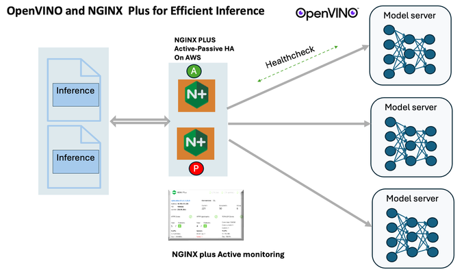
Introduction In the realm of artificial intelligence (AI) and machine learning (ML), the need for scalable and efficient AI inference solutions is paramount. As organizations deploy increasingly complex AI models to solve real-world problems, ensuring that these models can handle high volumes of inference requests becomes critical. NGINX Plus serves as a powerful ally in managing incoming traffic efficiently. As a high-performance web server and reverse proxy server, NGINX Plus is adept at load balancing and routing incoming HTTP and TCP traffic across multiple instances of AI model serving environments. The OpenVINO Model Server, powered by Intel's OpenVINO toolkit, is a versatile inference server supporting various deep learning frameworks and hardware acceleration technologies. It allows developers to deploy and serve AI models efficiently, optimizing performance and resource utilization. When combined with NGINX Plus capabilities, developers can create resilient and scalable AI inference solutions capable of handling high loads and ensuring high availability. Health checks allow NGINX Plus to continuously monitor the health of the upstream OVMS instances. If an OVMS instance becomes unhealthy or unresponsive, NGINX Plus can automatically route traffic away from it, ensuring that inference requests are processed only by healthy OVMS instances. Health checks provide real-time insights into the health status of OVMS instances. Administrators can monitor key metrics such as response time, error rate, and availability, allowing them to identify and address issues proactively before they impact service performance. In this article, we'll delve into the symbiotic relationship between the OpenVINO Model Server, and NGINX Plus to construct a robust and scalable AI inference solution. We'll explore setting up the environment, configuring the model server, harnessing NGINX Plus for load balancing, and conducting testing. By the end, readers will gain insights into how to leverage Docker, the OpenVINO Model Server, and NGINX Plus to build scalable AI inference systems tailored to their specific needs. Flow explanation: Now, let's walk through the flow of a typical inference request. When a user submits an image of a zebra for inference, the request first hits the NGINX load balancer. The load balancer then forwards the request to one of the available OpenVINO Model Server containers, distributing the workload evenly across multiple containers. The selected container processes the image using the optimized deep-learning model and returns the inference results to the user. In this case, the object is named zebra. OpenVINO™ Model Server is a scalable, high-performance solution for serving machine learning models optimized for Intel® architectures. The server provides an inference service via gRPC, REST API, or C API -- making it easy to deploy new algorithms and AI experiments. You can visit https://hub.docker.com/u/openvino for reference. Setting up: We'll begin by deploying model servers within containers. For this use case, I'm deploying the model server on a virtual machine (VM). Let's outline the steps to accomplish this: Get the docker image for OpenVINO ONNX run time docker pull openvino/onnxruntime_ep_ubuntu20 You can also visit https://docs.openvino.ai/nightly/ovms_docs_deploying_server.html for OpenVINO model server deployment in a container environment. Begin by creating a docker-compose file following the structure below: https://raw.githubusercontent.com/f5businessdevelopment/F5openVino/main/docker-compose.yml version: '3' services: resnet1: image: openvino/model_server:latest command: > --model_name=resnet --model_path=/models/resnet50 --layout=NHWC:NCHW --port=9001 volumes: - ./models:/models ports: - "9001:9001" resnet2: image: openvino/model_server:latest command: > --model_name=resnet --model_path=/models/resnet50 --layout=NHWC:NCHW --port=9002 volumes: - ./models:/models ports: - "9002:9002" # Add more services for additional containers resnet3: image: openvino/model_server:latest command: > --model_name=resnet --model_path=/models/resnet50 --layout=NHWC:NCHW --port=9003 volumes: - ./models:/models ports: - "9003:9003" resnet4: image: openvino/model_server:latest command: > --model_name=resnet --model_path=/models/resnet50 --layout=NHWC:NCHW --port=9004 volumes: - ./models:/models ports: - "9004:9004" resnet5: image: openvino/model_server:latest command: > --model_name=resnet --model_path=/models/resnet50 --layout=NHWC:NCHW --port=9005 volumes: - ./models:/models ports: - "9005:9005" resnet6: image: openvino/model_server:latest command: > --model_name=resnet --model_path=/models/resnet50 --layout=NHWC:NCHW --port=9006 volumes: - ./models:/models ports: - "9006:9006" resnet7: image: openvino/model_server:latest command: > --model_name=resnet --model_path=/models/resnet50 --layout=NHWC:NCHW --port=9007 volumes: - ./models:/models ports: - "9007:9007" resnet8: image: openvino/model_server:latest command: > --model_name=resnet --model_path=/models/resnet50 --layout=NHWC:NCHW --port=9008 volumes: - ./models:/models ports: - "9008:9008" Make sure you have Docker and Docker Compose installed on your system. Place your model files in the `./models/resnet50` directory on your local machine. Save the provided Docker Compose configuration to a file named `docker-compose.yml`. Run the following command in the directory containing the `docker-compose.yml` file to start the services: docker-compose up -d You can now access the OpenVINO Model Server instances using the specified ports (e.g., `http://localhost:9001` for `resnet1` and `http://localhost:9002` for `resnet2`). - Ensure that the model files are correctly placed in the `./models/resnet50` directory before starting the services. Set up an NGINX Plus proxy server. You can refer to https://docs.nginx.com/nginx/admin-guide/installing-nginx/installing-nginx-plus/ for NGINX Plus installation also You have the option to configure VMs with NGINX Plus on AWS by either: Utilizing the link provided below, which guides you through setting up NGINX Plus on AWS via the AWS Marketplace: NGINX Plus on AWS Marketplace or Following the instructions available on GitHub at the provided repository link. This repository facilitates spinning up VMs using Terraform on AWS and deploying VMs with NGINX Plus under the GitHub repository - F5 OpenVINO The NGINX Plus proxy server functions as a proxy for upstream model servers. Within the upstream block, backend servers (model_servers) are defined along with their respective IP addresses and ports. In the server block, NGINX listens on port 80 to handle incoming HTTP/2 requests targeting the specified server name or IP address. Requests directed to the root location (/) are then forwarded to the upstream model servers utilizing the gRPC protocol. The proxy_set_header directives are employed to maintain client information integrity while passing requests to the backend servers. Ensure to adjust the IP addresses, ports, and server names according to your specific setup. Here is an example configuration that is also available at GitHubhttps://github.com/f5businessdevelopment/F5openVino upstream model_servers { server 172.17.0.1:9001; server 172.17.0.1:9002; server 172.17.0.1:9003; server 172.17.0.1:9004; server 172.17.0.1:9005; server 172.17.0.1:9006; server 172.17.0.1:9007; server 172.17.0.1:9008; zone model_servers 64k; } server { listen 80 http2; server_name 10.0.0.19; # Replace with your domain or public IP location / { grpc_pass grpc://model_servers; health_check type=grpc grpc_status=12; # 12=unimplemented proxy_set_header Host $host; proxy_set_header X-Real-IP $remote_addr; proxy_set_header X-Forwarded-For $proxy_add_x_forwarded_for; } } If you are using gRPC with SSL please refer to the detailed configuration at NGINX Plus SSL Configuration Here is the explanation: upstream model_servers { server 172.17.0.1:9001; # Docker bridge network IP and port for your container server 172.17.0.1:9002; # Docker bridge network IP and port for your container .... .... } This section defines an upstream block named model_servers, which represents a group of backend servers. In this case, there are two backend servers defined, each with its IP address and port. These servers are typically the endpoints that NGINX will proxy requests to. server { listen 80 http2; server_name 10.1.1.7; # Replace with your domain or public IP This part starts with the main server block. It specifies that NGINX should listen for incoming connections on port 80 using the HTTP/2 protocol (http2), and it binds the server to the IP address 10.1.1.7. Replace this IP address with your domain name or public IP address. location / { grpc_pass grpc://model_servers; health_check type=grpc grpc_status=12; # 12=unimplemented proxy_set_header Host $host; proxy_set_header X-Real-IP $remote_addr; proxy_set_header X-Forwarded-For $proxy_add_x_forwarded_for; } Within the location/block, NGINX defines how to handle requests to the root location. In this case, it's using gRPC (grpc_pass grpc://model_servers;) to pass the requests to the upstream servers defined in the model_servers block. The proxy_set_header directives are used to set headers that preserve client information when passing requests to the backend servers. These headers include Host, X-Real-IP, and X-Forwarded-For. Health checks with type=grpc enable granular monitoring of individual gRPC services and endpoints. You can verify the health of specific gRPC methods or functionalities, ensuring each service component is functioning correctly. In summary, this NGINX configuration sets up a reverse proxy server that listens for HTTP/2 requests on port 80 and forwards them to backend servers (model_servers) using the gRPC protocol. It's commonly used for load balancing or routing requests to multiple backend servers. Inference Testing: This is how you can conduct testing. On the client side, we utilize a script named predict.py. Below is the script for reference # Import necessary libraries import numpy as np from classes import imagenet_classes from ovmsclient import make_grpc_client # Create a gRPC client to communicate with the server # Replace "10.1.1.7:80" with the IP address and port of your server client = make_grpc_client("10.1.1.7:80") # Open the image file "zebra.jpeg" in binary read mode with open("zebra.jpeg", "rb") as f: img = f.read() # Send the image data to the server for prediction using the "resnet" model output = client.predict({"0": img}, "resnet") # Extract the index of the predicted class with the highest probability result_index = np.argmax(output[0]) # Print the predicted class label using the imagenet_classes dictionary print(imagenet_classes[result_index]) This script imports necessary libraries, establishes a connection to the server at the specified IP address and port, reads an image file named "zebra.jpeg," sends the image data to the server for prediction using the "resnet" model, retrieves the predicted class index with the highest probability, and prints the corresponding class label. Results: Execute the following command from the client machine. Here, we are transmitting this image of Zebra to the model server. python3 predict.py zebra.jpg #run the Inference traffic zebra. The prediction output is 'zebra'. Let's now examine the NGINX Plus logs cat /var/log/nginx/access.log 10.1.1.7 - - [13/Apr/2024:00:18:52 +0000] "POST /tensorflow.serving.PredictionService/Predict HTTP/2.0" 200 4033 "-" "grpc-python/1.62.1 grpc-c/39.0.0 (linux; chttp2)" This log entry shows that a POST request was made to the NGINX server at the specified timestamp, and the server responded with a success status code (200). The request was made using gRPC, as indicated by the user agent string. Conclusion: Using NGINX Plus, organizations can achieve a scalable and efficient AI inference solution. NGINX Plus can address disruptions caused by connection timeouts/errors, sudden spikes in request rates, or changes in network topology. OpenVINO Model Server optimizes model performance and inference speed, utilizing Intel hardware acceleration for enhanced efficiency. NGINX Plus acts as a high-performance load balancer, distributing incoming requests across multiple model server instances for improved scalability and reliability. Together, this enables seamless scaling of AI inference workloads, ensuring optimal performance and resource utilization. You can look at this video for reference: https://youtu.be/Sd99woO9FmQ References: https://hub.docker.com/u/openvino https://docs.nginx.com/nginx/deployment-guides/amazon-web-services/high-availability-keepalived/ https://www.nginx.com/blog/nginx-1-13-10-grpc/ https://github.com/f5businessdevelopment/F5openVino.git https://docs.openvino.ai/nightly/ovms_docs_deploying_server.html323Views0likes0CommentsF5 Distributed Cloud – Multiple custom certificates for HTTP/TCP LB
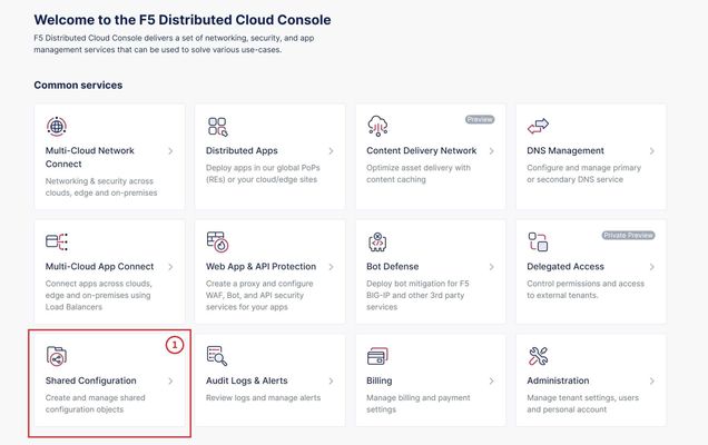
TLS Certificate A TLS certificate is a digital certificate signed by a trusted Certificate Authority (CA) that will authenticate the identity of the certificate owner. It is required to encrypt and secure traffic over the internet using Public Key Infrastructure (PKI). F5 Distributed Cloud (F5 XC) had already implemented the ability to choose between automatic TLS certificate management and attaching a custom TLS certificate (aka Bring Your Own Certificate) in its HTTP/TCP load balancer configurations. Now a new feature is added enabling customers to attach multiple custom TLS certificates to a single HTTP/TCP load balancer, this will allow them to host multiple domains with different certificates from a single load balancer so that they can optimize costs or simplify configuration. Also, now TLS certificates can be shared across multiple LBs and customers can view and manage their TLS certificates and intermediate certificate chains as standalone objects from a centralized place. Note: This feature is supported for the HTTP/TCP LBs advertised either on Regional Edges (REs) or on Customer Edge (CE). Configuration Step1: Create TLS certificate object in XC console Select `Shared Configuration` service from the home page of XC console. Select `Certificate Management` from the left menu and select `TLS Certificates`, Click `Add TLS Certificate`. Note: Certificate Management configuration can be done either from Multi-Cloud App Connect, Web App & API Protection, Distributed Apps, or Shared Configuration services. Configure certificate properties and upload the certificate. Note: Supported certificate formats are PEM and PKCS#12 (aka P12) Optionally, configure OCSP stapling and intermediate certificate chain. OCSP (Online Certificate Status Protocol) is used to determine the revocation state of digital certificates. For more information on OCSP stapling follow the documentation Certificate Chain of trust refers to all the certificates that are linked together in an ordered fashion to validate the legitimacy of the server certificate. There are 3 components in this certificate chain: Root certificate: This certificate belongs to Root Certificate Authority (CA) and are self-signed. Intermediate certificate: This certificate belongs to intermediate CA and are signed by Root CA, Intermediate CA signs the certificates on behalf of Root CA and there can be one or more Intermediate CA in a certificate chain of trust. Leaf/server certificate: This certificate belongs to the web server to establish secure connection or authenticating clients reaching to the server, this can either be signed by a Root CA or an Intermediate CA. Above screenshot shows the list of TLS Certificates, one certificate is signed by the Root CA and is created in personal namespace (demo) while the other certificate is signed by the Intermediate CA and is created in `shared namespace` (Note: objects created in shared namespace can be used across all other namespaces). Step2: Attach TLS certificates to the load balancer (HTTP/TCP) Note: In this demonstration, we are attaching the TLS certificates to the HTTP LB Click on `Load Balancers`, from the left menu and select `HTTP Load Balancers`. Click Add `HTTP Load Balancer`, Configure HTTP LB, enter valid domains as per the TLS certificates. Select ‘HTTPS with Custom Certificate’ option in ‘Load Balancer Type’ field, and in ‘TLS Configuration’ select `Multiple Certificates` option. Click on ‘Configure’ and attach the above created TLS certificates by keeping ‘TLS Security Level’ as `High`. We have already created origin pools for our two domains and added those origin pool members to the LB with the help of ‘Routes’ as shown inthe screenshots below. (Applications deployed on origin servers are httpbin and dvga) You could either advertise this LB to the internet which is also a default setting or can customize it to be advertised on a CE site. For this demo we have advertised the LB to 'Internet'. Click `Save and Exit`. Note:Each LB has a certificate expiration date, and in case of multiple certs this value is automatically set to the expiry date of its certificate which is expiring earlier. Similarly, you can configure TCP LB as well with multiple custom TLS certificates. For more details on how to configure TCP LB refer to the document. Step3: Check the server certificate details by clicking padlock next to the URL Open the browser and check for the LB domains, Connection should be shown as secure. Note: In this demo we are using local domain names and TLS Certificates, so we have manually added the custom local `Root CA` certificate to the browser and edited the hosts file to map VIP with our domain names. When the certificate expiry date approaches near, you will be notified with alerts. You can see active alerts by navigating to `Notifications -> Alerts` section from the menu on the left side or by clicking the bell icon on top right corner of the XC console. Based on the alerts received, you can renew the certificate expiration date and upload it again to the existing XC’s TLS cert object to reuse it instead of creating a new object. Conclusion: In the above demo, you have seen using XC console how easy it is to manage your multiple custom TLS certificates from a centralized place.2.8KViews3likes0Comments