kubernetes
58 TopicsF5 NGINX Gateway Fabric 2.7 - Securing AI Workloads and Extending BIG-IP into Kubernetes
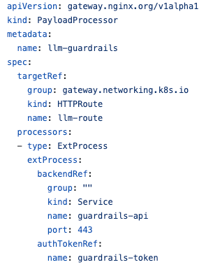
NGINX Gateway Fabric 2.7 builds on the momentum of 2.6 with a strong focus on AI security, WAF lifecycle management, and tighter integration across the F5 portfolio. From protecting AI inference traffic to bringing BIG-IP integration to the Gateway API, this release extends enterprise-grade capabilities natively into Kubernetes. Here's what's new. Securing AI interactions with F5 AI Guardrails What's new: We have enhanced the Gateway API Inference Extension in NGINX Gateway Fabric by adding support for Gateway API-aligned payload processing for AI traffic. This enables prompts and responses in OpenAI-compatible inference flows to be inspected and protected using external processors such as F5 AI Guardrails. As a result, platform teams can apply security controls to AI inference traffic while staying aligned with Gateway API patterns. Why it matters: As organisations rush to ship AI-powered applications, securing the prompts and responses flowing to and from models becomes critical. Applying inspection at the Gateway means teams can protect these workloads without touching application code, keeping security consistent and centrally managed while staying true to Gateway API patterns. F5 WAF for NGINX Phase 2: Policy Lifecycle Manager What's new: Building on the F5 WAF support introduced in 2.6, this second phase lets you define WAF policies as Kubernetes custom resources directly. The entire policy lifecycle now happens inside Kubernetes, making it self-contained and cluster-scoped, and helping teams adopt GitOps workflows with standard tooling such as Argo CD and Flux. Why it matters: Phase 1 brought WAF policies to the Gateway API through the ClickOps flow. Phase 2 makes policy management fully declarative and native to Kubernetes, giving teams a version-controlled, auditable approach that fits the workflows they already trust, with no external management plane required. GatewayLink: BIG-IP/CIS Integration What's new: GatewayLink provides a declarative integration between BIG-IP/CIS and NGINX Gateway Fabric. As part of this, we're introducing a new `ExternalLoadBalancer` resource, designed to be extensible to other F5 load balancers in the future. Stay tuned for more on that. The integration requires no new CRD and no code changes on the CIS side. When CIS is present in the cluster, NGF handles the integration as part of the Gateway deployment. CIS populates the IPs of the NGINX pods and configures a virtual server on BIG-IP that load-balances traffic to the NGF pods. Why it matters: This brings the proven BIG-IP integration story to the Gateway API world with zero disruption to existing CIS deployments. The extensible `ExternalLoadBalancer` resource also lays the groundwork for supporting additional load balancers down the line, giving teams a consistent, declarative integration model. Since microservices in Kubernetes are ephemeral, IP address keeps changing. Without this integration, BIG-IP maybe forwarding traffic to services inside Kubernetes whose IP maybe changing constantly. Through GatewayLink, BIG-IP can forward traffic to a predictable, stable endpoint inside Kubernetes, which is NGINX Gateway Fabric. External Authentication with HTTPExternalAuthFilter What's new: This release adds a Gateway API-conformant way to authenticate requests via an external authorization proxy before routing traffic to backend applications, through the new `ExternalAuth` filter. Under the hood, this adds support for NGINX's `http_auth_request` module to enable external authentication checks. Why it matters: External auth is a common requirement for enterprise applications, and doing it in a Gateway API-conformant way means teams get a portable, standards-based approach rather than relying on custom snippets or bespoke solutions. It integrates cleanly alongside NGF's existing authentication capabilities. Gateway API 1.6 Conformance What’s new: TCPRoute and UDPRoute move from v1alpha2 to v1, following their graduation out of experimental in Gateway API 1.6. Multiple L4 routes can now attach to the same listener, though only the oldest is used. The conformance suite passes with all the new TCP and UDP tests. TLS listeners also gain Terminate mode, alongside the existing passthrough. Why it matters: A stable API version is what a platform team waits for before it puts L4 traffic on a Gateway in production - v1alpha2 is a fine place to experiment and a hard thing to standardize on. Your TCP and UDP routes now sit at the same API maturity as your HTTP ones, and Terminate mode means a TLS listener can end the connection at the Gateway rather than passing it through untouched. HTTP/2 to Service Support What's new: NGINX Gateway Fabric now supports HTTP/2 as a client to upstream services, built on the HTTP/2 client capability recently added to NGINX. Why it matters: HTTP/2 to upstreams unlocks better performance and more efficient connection handling between NGF and backend services, ensuring modern protocol support end to end rather than just at the edge. Bug Fixes and Smaller Enhancements This release also includes multiple stability improvements, bug fixes, and community-driven enhancements, including: * Support for Cluster IP services: NGF can now work with `ClusterIP` services, giving teams more flexibility in how they wire up their backends. Thanks to SidharathBansal on GitHub for this contribution. * Least time load balancing moves to OSS: NGF now supports the `least_time` load balancing method in open source, which routes requests to the upstream with the lowest average response time. Thanks to yogarajalakshmi-s on GitHub for this contribution. * F5 WAF Security Monitoring is now available on NGINX Instance Manager Head over to the [GitHub release page](https://github.com/nginx/nginx-gateway-fabric/releases) and our [public release docs](https://docs.nginx.com/nginx-gateway-fabric/) for the full picture. You can also follow [this link](https://docs.nginx.com/nginx-gateway-fabric/) to upgrade NGINX Gateway Fabric, and check out the [Kubernetes NGINX landing page](https://kubernetes.nginx.org/) to learn more about migrating from NGINX Ingress Controller to NGINX Gateway Fabric. Thanks to our Community Finally, this release blog focuses on the new enterprise-grade features in NGINX Gateway Fabric, but NGINX Gateway Fabric 2.7 also includes some significant open source features built by the team, with contributions from our open source community. For more info on these, read through our community blog here: https://blog.nginx.org/blog/nginx-gateway-fabric-2-7-gateway-api-1-6-conformance-external-authentication-and-fewer-snippets We're proud of what the team put together here, and we can't wait to share it with the community and our Customers.54Views1like0CommentsF5 NGINX Ingress Controller 5.6 – Improved WAF Management, New Resources and Improved Config Safety
NGINX Ingress Controller 5.6 delivers a strong set of security and traffic management enhancements, from flexible WAF policy sourcing to native OpenID Connect support. This release gives SecOps and platform teams more choice in how they author and enforce policies, while closing long-standing gaps that previously required snippets and workarounds. Here's what's new. WAF via Management Plane: NGINX One Console, NIM, and HTTP Server What's new: NGINX Ingress Controller now supports pulling pre-compiled WAF policies from a range of sources, giving teams the flexibility to source policies from wherever they already work, covering both ClickOps and GitOps. Teams can source pre-compiled WAF policies from any of the following: NGINX One Console (N1C) — for teams authoring and compiling policies via the NGINX One Console NGINX Instance Manager (NIM) — for teams using the NIM platform to manage and compile policies A HTTP Server - For teams running CICD and have their policies stores in a separate HTTP endpoint. Why it matters: SecOps teams can own and manage policies through the tools they already use, while application teams keep moving fast. This flexible retrieval model meets teams where they are, whether that's a centralised team managing policies through NGINX One Console or a distributed setup using NIM. WAF Policy Lifecycle Management What's new: NGINX Ingress Controller adds Policy Lifecycle Management for WAF, letting you define WAF policies as Kubernetes custom resources directly. The entire policy lifecycle happens inside Kubernetes, making it self-contained and cluster-scoped, and helping teams adopt GitOps workflows with standard tooling such as Argo CD and Flux. Why it matters: Managing policy natively in Kubernetes makes it declarative, version-controlled, and auditable, giving teams a consistent approach that fits the workflows they already trust, with no external management plane required. Native OpenID Connect (OIDC) Module What's new: NGINX Ingress Controller now supports native OpenID Connect using the new NGINX Plus OIDC module. This is offered as an additional option alongside the existing njs-based approach, giving teams the choice of which to use. Why it matters: The native NGINX Plus module delivers a more robust, better-integrated, and easier-to-manage authentication experience, while teams that rely on the njs option can continue using it. It's about giving teams more choice in how they implement standards-based identity and authentication. HSTS Policy for VirtualServer, VirtualServerRoute, and Ingress What's new: HSTS can now be configured natively across VirtualServer, VirtualServerRoute, and Ingress resources. This has been a highly requested feature that previously required snippets and other workarounds. Why it matters: HSTS is an important part of enforcing secure connections, and doing it natively removes the need for fragile snippet-based approaches. Teams get a clean, Kubernetes-native way to enforce HTTPS and improve their security posture. Additional Annotations to Ease ingress-nginx Migrations What's new: NGINX Ingress Controller adds support for additional annotations to ease migrations from ingress-nginx, including `custom-http-errors` and `upstream-vhost`. As part of this, users can now manually set the `Host` and `X-Forwarded-*` headers and include custom error pages, giving teams more control over how requests are presented to backend applications. Why it matters: Header handling and custom error pages are the kind of details that sound simple but quickly get complicated in real environments. Supporting these annotations natively closes gaps that previously pushed teams toward custom snippets, and smooths the path for teams migrating from ingress-nginx. Logging Enhancements What's new: NGINX Ingress Controller now includes `resource_namespace` in NIC error logs. Why it matters: Adding namespace context to error logs makes troubleshooting faster and easier, especially in multi-team environments where the same controller serves many namespaces. Stability and Bug Fixes This release also includes multiple stability improvements and bug fixes. Head over to the [GitHub release page](https://github.com/nginx/kubernetes-ingress/releases) and our [public release docs](https://docs.nginx.com/nginx-ingress-controller/) for the full picture. A Thank You to our Community Finally, this release blog focuses on the new enterprise-grade features in F5 NGINX Ingress Controller, but NIC 2.6 also includes some significant open source features built by the team, with contributions from our open source community. For more info on these, read through our community blog here: https://blog.nginx.org/blog/nginx-ingress-controller-5-6-hsts-without-snippets-a-faster-start-on-large-clusters-and-improved-configuration-safety. We're proud of what the team put together here, and we can't wait to share it with the community and our Customers.55Views1like0CommentsDeploying the F5 AI Security Certified OpenShift Operator: A Validated Playbook
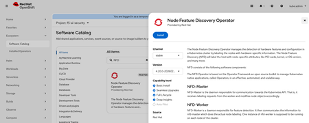
Introduction As enterprises race to deploy Large Language Models (LLMs) in production, securing AI workloads has become as critical as securing traditional applications. The F5 AI Security Operator installs two products on your cluster — F5 AI Guardrails and F5 AI Red Team — both powered by CalypsoAI. Together they provide inline prompt/response scanning, policy enforcement, and adversarial red-team testing, all running natively on your own OpenShift cluster. This article is a validated deployment runbook for F5 AI Security on OpenShift (version 4.20.14) with NVIDIA GPU nodes. It is based on the official Red Hat Operator installation baseline, in a real lab deployment on a 3×A40 GPU cluster. If you follow these steps in order, you will end up with a fully functional AI Security stack, avoiding the most common pitfalls along the way. What Gets Deployed F5 AI Security consists of four main components, each running in its own OpenShift namespace: Component Namespace Role Moderator + PostgreSQL cai-moderator Web UI, API gateway, policy management, and backing database Prefect Server + Worker prefect Workflow orchestration for scans and red-team runs AI Guardrails Scanner cai-scanner Inline scanning against your OpenAI-compatible LLM endpoint AI Red Team Worker cai-redteam GPU-backed adversarial testing; reports results to Moderator via Prefect The Moderator is CPU-only. The Scanner and Red Team Worker can leverage GPUs depending on the policies and models you configure. Infrastructure Requirements Before you begin, verify your cluster meets these minimums: CPU / Control Node 16 vCPUs, 32 GiB RAM, x86_64, 100 GiB persistent storage Worker Nodes (per GPU-enabled component) 4 vCPUs, 16 GiB RAM (32 GiB recommended for Red Team), 100 GiB storage GPU Nodes AI Guardrails: CUDA-compatible GPU, minimum 24 GB VRAM, 100 GiB storage AI Red Team: CUDA-compatible GPU, minimum 48 GB VRAM, 200 GiB storage GPU must NOT be shared with other workloads Verify your cluster: # Check nodes oc get nodes -o wide # Check GPU allocatable resources oc get node -o jsonpath='{range .items[*]}{.metadata.name}{"\t"}{.status.allocatable.nvidia\.com/gpu}{"\n"}{end}' # Check available storage classes oc get storageclass NAME PROVISIONER RECLAIMPOLICY VOLUMEBINDINGMODE ALLOWVOLUMEEXPANSION AGE lvms-vg1 (default) topolvm.io Delete WaitForFirstConsumer true 15d Step 1 — Install Prerequisites 1.1 Node Feature Discovery (NFD) Operator NFD labels your nodes with hardware capabilities, which NVIDIA GPU Operator relies on to target the right nodes. OpenShift Console → Ecosystem → Software Catalog → Search Node Feature Discovery Operator → Install After installation: Installed Operators → Node Feature Discovery → Create NodeFeatureDiscovery → Accept defaults Verify: oc get pods -n openshift-nfd oc get node --show-labels | grep feature.node.kubernetes.io || true 1.2 NVIDIA GPU Operator OpenShift Console → Ecosystem → Software Catalog → Search GPU Operator → Install After installation: Installed Operators → NVIDIA GPU Operator → Create ClusterPolicy → Accept defaults Verify: oc get pods -n nvidia-gpu-operator oc describe node <gpu-node> | grep -i nvidia nvidia-smi</gpu-node> Step 2 — Install F5 AI Security Operator Prerequisites: You will need registry credentials and a valid license from the F5 AI Security team before proceeding. Contact F5 Sales: https://www.f5.com/products/get-f5 2.1 Create the Namespace and Pull Secret export DOCKER_USERNAME='<registry-username>' export DOCKER_PASSWORD='<registry-password>' export DOCKER_EMAIL='<your-email>' oc new-project f5-ai-sec oc create secret docker-registry regcred \ -n f5-ai-sec \ --docker-username=$DOCKER_USERNAME \ --docker-password=$DOCKER_PASSWORD \ --docker-email=$DOCKER_EMAIL</your-email></registry-password></registry-username> 2.2 Install from OperatorHub OpenShift Console → Ecosystem → Software Catalog → Search F5 AI Security Operator → Install into namespace f5-ai-sec Verify your F5 AI Security Operator: # Verify the controller-manager pod is Running oc -n f5-ai-sec get pods # NAME READY STATUS RESTARTS AGE # controller-manager-6f784bd96d-z6sbh 1/1 Running 1 43s # Verify the CSV reached Succeeded phase oc -n f5-ai-sec get csv # NAME DISPLAY VERSION PHASE # f5-ai-security-operator.v0.4.3 F5 Ai Security Operator 0.4.3 Succeeded # Verify the CRD is registered oc -n f5-ai-sec get crd | grep ai.security.f5.com # securityoperators.ai.security.f5.com 2.3 Deploy the SecurityOperator Custom Resource After installation: Installed Operators → F5 AI Security Operator → Create SecurityOperator Choose YAML and copy the below Custom Resource Template in there, changing select values to match your installation. apiVersion: ai.security.f5.com/v1alpha1 kind: SecurityOperator metadata: name: security-operator-demo namespace: f5-ai-sec spec: registryAuth: existingSecret: "regcred" # Internal PostgreSQL — convenient for labs, not recommended for production postgresql: enabled: true values: postgresql: auth: password: "pass" jobManager: enabled: true moderator: enabled: true values: env: CAI_MODERATOR_BASE_URL: https://<your-hostname> secrets: CAI_MODERATOR_DB_ADMIN_PASSWORD: "pass" CAI_MODERATOR_DEFAULT_LICENSE: "<valid_license_from_f5>" scanner: enabled: true redTeam: enabled: true</valid_license_from_f5></your-hostname> Key values to customize: Field What to set CAI_MODERATOR_BASE_URL Your cluster's public hostname for the UI (e.g., https://aisec.apps.mycluster.example.com ) CAI_MODERATOR_DEFAULT_LICENSE License string provided by F5 CAI_MODERATOR_DB_ADMIN_PASSWORD DB password — must match the value set in the PostgreSQL block For external PostgreSQL (recommended for production), replace the postgresql block with: moderator: values: env: CAI_MODERATOR_DB_HOST: <my-external-db-hostname> secrets: CAI_MODERATOR_DB_ADMIN_PASSWORD: <my-external-db-password></my-external-db-password></my-external-db-hostname> Verify your F5 AI Security Operator: oc -n f5-ai-sec get securityoperator oc -n f5-ai-sec get securityoperator security-operator-demo -o yaml | sed -n '/status:/,$p' Step 3 — Required OpenShift Configuration This is where most deployments hit problems. OpenShift's default restricted Security Context Constraint (SCC) blocks these containers from running. You must explicitly grant anyuid to each service account. 3.1 Apply SCC Policies oc adm policy add-scc-to-user anyuid -z cai-moderator-sa -n cai-moderator oc adm policy add-scc-to-user anyuid -z default -n cai-moderator oc adm policy add-scc-to-user anyuid -z default -n prefect oc adm policy add-scc-to-user anyuid -z prefect-server -n prefect oc adm policy add-scc-to-user anyuid -z prefect-worker -n prefect oc adm policy add-scc-to-user anyuid -z cai-scanner -n cai-scanner oc adm policy add-scc-to-user anyuid -z cai-redteam-worker -n cai-redteam 3.2 Force PostgreSQL to Restart (if Stuck at 0/1) If PostgreSQL was stuck before the SCC was applied, bounce it manually: oc -n cai-moderator scale sts/cai-moderator-postgres-cai-postgresql --replicas=0 oc -n cai-moderator scale sts/cai-moderator-postgres-cai-postgresql --replicas=1 3.3 Restart All Components oc -n cai-moderator rollout restart deploy oc -n prefect rollout restart deploy oc -n cai-scanner rollout restart deploy oc -n cai-redteam rollout restart deploy 3.4 Verify ➜ oc -n cai-moderator get statefulset NAME READY AGE cai-moderator-postgres-cai-postgresql 1/1 3d4h ➜ oc -n cai-moderator get pods | grep postgres cai-moderator-postgres-cai-postgresql-0 1/1 Running 0 3d4h ➜ oc -n cai-moderator get pods | grep cai-moderator cai-moderator-75c47fc9db-sl8t2 1/1 Running 0 3d4h cai-moderator-postgres-cai-postgresql-0 1/1 Running 0 3d4h ➜ oc -n cai-moderator get svc NAME TYPE CLUSTER-IP EXTERNAL-IP PORT(S) AGE cai-moderator ClusterIP 172.30.123.197 <none> 5500/TCP,8080/TCP 3d4h cai-moderator-headless ClusterIP None <none> 8080/TCP 3d4h cai-moderator-postgres-postgresql ClusterIP None <none> 5432/TCP 3d4h ➜ oc -n cai-moderator get endpoints Warning: v1 Endpoints is deprecated in v1.33+; use discovery.k8s.io/v1 EndpointSlice NAME ENDPOINTS AGE cai-moderator 10.130.0.139:8080,10.130.0.139:5500 3d4h cai-moderator-headless 10.130.0.139:8080 3d4h cai-moderator-postgres-postgresql 10.128.0.177:5432 3d4h</none></none></none> Step 4 — Create OpenShift Routes (Required for UI Access) The Moderator exposes two ports that must be routed separately: port 5500 for the UI and port 8080 for the /auth path. Skipping the auth route is the most common cause of the blank/black page issue. # UI route oc -n cai-moderator create route edge cai-moderator-ui \ --service=cai-moderator \ --port=5500 \ --hostname=<your-hostname> \ --path=/ # Auth route — required, or the UI will render blank oc -n cai-moderator create route edge cai-moderator-auth \ --service=cai-moderator \ --port=8080 \ --hostname=<your-hostname> \ --path=/auth</your-hostname></your-hostname> Verify all pods are running: oc get pods -n cai-moderator oc get pods -n cai-scanner oc get pods -n cai-redteam oc get pods -n prefect Access the UI Open https:// in a browser. Log in with the default credentials: admin / pass Log in and update the admin email address immediately. You should be able to log in successfully and see the Guardrails dashboard. Step 5 — Grant Prefect Worker Cluster-scope RBAC The Prefect worker watches Kubernetes Pods and Jobs at cluster scope to monitor scan and red-team workflow execution. Without this RBAC, prefect-worker fills its logs with 403 Forbidden errors. The Guardrails UI still loads, but scheduled workflows and Red Team runs will fail silently. # ClusterRole: allow prefect-worker to list/watch pods, jobs, and events cluster-wide oc apply -f - <<'YAML' apiVersion: rbac.authorization.k8s.io/v1 kind: ClusterRole metadata: name: prefect-worker-watch-cluster rules: - apiGroups: ["batch"] resources: ["jobs"] verbs: ["get","list","watch"] - apiGroups: [""] resources: ["pods","pods/log","events"] verbs: ["get","list","watch"] YAML # ClusterRoleBinding: bind to the prefect-worker ServiceAccount oc apply -f - <<'YAML' apiVersion: rbac.authorization.k8s.io/v1 kind: ClusterRoleBinding metadata: name: prefect-worker-watch-cluster subjects: - kind: ServiceAccount name: prefect-worker namespace: prefect roleRef: apiGroup: rbac.authorization.k8s.io kind: ClusterRole name: prefect-worker-watch-cluster YAML # Restart to pick up the new permissions oc -n prefect rollout restart deploy/prefect-worker Verify RBAC errors are gone: oc -n prefect logs deploy/prefect-worker --tail=200 \ | egrep -i 'forbidden|rbac|permission|denied' \ || echo "OK: no RBAC errors detected" oc get clusterrolebinding prefect-worker-watch-cluster LlamaStack Integration F5 AI Security works alongside any OpenAI-compatible LLM inference endpoint. In our lab we pair it with LlamaStack running a quantized Llama 3.2 model on the same OpenShift cluster — F5 AI Guardrails then scans every prompt and response inline before it reaches your application. A dedicated follow-up post will walk through the full LlamaStack deployment and end-to-end integration in detail. Stay tuned. Summary Deploying F5 AI Security on OpenShift is straightforward once you know the OpenShift-specific friction points: SCC policies, the dual-route requirement, and the Prefect cluster-scope RBAC. Following this runbook in sequence — prerequisites, operator install, SCC grants, routes, Prefect RBAC — gets you to a fully operational AI guardrailing stack in a single pass. If you run into anything not covered here, drop a comment below. Tested on: OpenShift 4.20.14 · F5 AI Security Operator v0.4.3 · NVIDIA A40 GPUs · LlamaStack with Llama-3.2-1B-Instruct-quantized.w8a8 Additional Resources F5 AI Security Operator — Red Hat Catalog1.3KViews2likes1CommentSecuring AI with F5 AI Guardrails and Nutanix Enterprise AI
Enterprises are rapidly moving from AI experimentation to production-grade deployments, using Kubernetes to deliver and scale AI services consistently across environments. As AI workloads become embedded in business-critical workflows, new risks emerge—particularly at runtime. Generative AI systems can expose sensitive data, generate responses to restricted topics, or be manipulated through prompt injection and jailbreak techniques during user interactions. The challenge is no longer just how to deploy AI models, but how to control AI behavior in real-time—without adding operational complexity or slowing innovation. F5 and Nutanix address this challenge together by combining Nutanix Enterprise AI (NAI) with F5 AI Guardrails. Nutanix Enterprise AI provides a Kubernetes-based platform to deploy and operate AI models and inference services at scale, while F5 AI Guardrails enforces real-time security and policy controls on AI interactions. 🎬 See the Joint Solution in Action ✨ NEW✨🎬 Watch this demo video to see F5 AI Guardrails work seamlessly together with Nutanix Enterprise AI (NAI) Agent Gateway Unified Endpoint (New in NAI v2.7) to secure LLM inference at scale. 🎬 Watch this demo video to see how F5 and Nutanix work together to deliver secure, trustworthy, enterprise‑ready AI—running side by side on Nutanix Kubernetes Platform (NKP) deployed on Nutanix Infrastructure. F5 AI Guardrails Overview F5 AI Guardrails provides runtime security and governance for AI applications, models, and agents by enforcing policy‑based controls on how AI interacts with users and data. It includes a broad set of out‑of‑the‑box guardrails that enable organizations to immediately begin securing and governing AI interactions from day one. These built‑in guardrails address common AI risks such as prompt injection, jailbreaks, PII exposure, restricted topics, and more. In addition to built‑in guardrails, F5 AI Guardrails supports custom guardrails, allowing teams to tailor policy enforcement to specific use cases. One option for defining custom guardrails is through natural‑language policy creation, guided by an integrated F5 AI Assistant. The AI Assistant reviews and refines guardrail definitions using F5 best practices, ensuring that descriptions are clear, concise, and consistently structured for optimal performance. AI Guardrails simplifies AI observability by providing continuous visibility and traceability across AI interactions, with audit‑ready observability, scanning, and logging to support governance and compliance. As part of the F5 Application Delivery and Security Platform (ADSP), AI Guardrails delivers runtime protection for AI models, agents, and connected data, extending F5’s application delivery, security, and observability capabilities across applications and APIs. https://www.f5.com/products/ai-guardrails Nutanix Enterprise AI (NAI) Overview Nutanix Enterprise AI (NAI) is a cloud‑native, Kubernetes‑based AI platform designed to help organizations run AI inference at scale. NAI is supported on CNCF‑certified Kubernetes platforms, including Nutanix Kubernetes Platform (NKP). It enables enterprises to deploy, manage, and operate AI models, inference endpoints, and AI agents through a single, unified management experience, allowing organizations to run AI consistently wherever they operate Kubernetes while maintaining enterprise control, security, and visibility. https://www.nutanix.com/products/nutanix-enterprise-ai F5 and Nutanix: Better Together Nutanix Enterprise AI provides a Kubernetes‑based platform for deploying, managing, and operating AI models, inference endpoints, and AI agents, while F5 AI Guardrails provides runtime security and governance for AI interactions. F5 AI Guardrails can run side by side with Nutanix Enterprise AI, with both solutions deployed on the same Nutanix Kubernetes Platform (NKP)–managed Kubernetes cluster, enabling them to operate on a common Kubernetes foundation. Together, F5 and Nutanix deliver secure, trustworthy, enterprise‑ready AI deployments by combining an enterprise AI platform with runtime AI security—enabling organizations to move fast with AI without losing control over security, compliance, and governance. 674Views2likes0Comments
Use MinIO AIStor in Kubernetes with BIG-IP Container Ingress Services for S3 data delivery
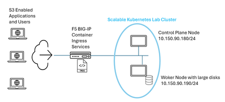
AIStor is a massively scalable S3 object storage solution, one which can exist outside or inside of Kubernetes (k8s) clusters. Modern workflows, including AI workflows, often gravitate to orchestrated container schemes, something to alleviate hands-on keyboard tasks. One example would be a “vanilla” k8s solution, the so-called upstream Kubernetes which reflects the original, unmodified, and open-source version of the Kubernetes codebase hosted by the Cloud Native Computing Foundation (CNCF). Popular as well are “opinionated” Kubernetes, solutions like RedHat OpenShift Container Platform (OCP) which can integrate enterprise-grade tools and can often install with thought-out default settings. Let’s consider a couple of examples of k8s workloads that might leverage highly performant in-the-cluster S3 object storage; the first could be an AI data delivery task. Data scientists can initiate machine learning jobs within k8s that access large, centralized datasets—often hundreds of gigabytes of image or text data—stored through S3. During AI training, compute pods read and process this data, then write the resulting model artifacts, such as checkpoints and weights, back via S3. Another example would be in the world of “Big Data” and analytics processing, chief among these examples would be Apache Spark jobs. ETL (Extract, Transform, Load) workloads running on Kubernetes consume raw log or database files from S3 storage. Processing frameworks, such as Spark clusters, transform the data and persist the output back to S3 in optimized formats like Parquet. With the need for scalable and performant S3 storage being made, the question is how to seamlessly access this “inside” Kubernetes S3 to all of the S3 application users that exist outside of Kubernetes. This is where a modern k8s ingress controller offering, such as BIG-IP Container Ingress Services (CIS), will shine. This article aims to set up a simple working Kubernetes lab environment, equipped with both AIStor inside k8s and a BIG-IP appliance, to demonstrate the ease of setup and streamlined S3 data delivery that can be offered. Build a Kubernetes lab with MinIO AIStor installed To keep aligned with a simple, quick-win philosophy, the simplest Kubernetes new deployment was conducted. This entailed installing on just a couple of hosts a modern Ubuntu operating system and then downloading the constituent components of a k8s control-plane node and worker node from the kubernetes.io website site. The CNCF fully documents this “build your own cluster” approach on their site. In production cases, a large node set, made up of multiple control-plane nodes and even more worker nodes is expected; within a learning-first oriented lab environment just two nodes were started with. In order to deploy the MinIO AIStor, a simple lab setup as depicted below was laid out. Note worker nodes in the Kubernetes cluster should have large, performant disks locally installed. This is important, when the time comes to use persistent volumes and the required persistent volume claims, to be described later, one does not want to cede performance by using an external storage solution, like a remote and shared legacy SAN as an example. Create MinIO DirectPV and assign your drives Simply put, Kubernetes is a container orchestration scheme, think of the difficulty of manually launching containers to run the entirety of a modern application. There could be many processes, leading to an eclectic set of different containers. The intelligence to launch the appropriate number of each container type, at the exact right time, and provide critical auto recovery around failed containers, forget about it, this job is best left for Kubernetes and not your hands and keyboard. In a nutshell, a container storage interface (CSI) driver is the “storage adapter” for Kubernetes. Kubernetes itself doesn’t know how to talk to storage systems, think AWS EBS, Azure Disk or NFS-based NAS appliances, as examples. The CSI driver is the plugin that translates Kubernetes requests into storage actions. Just like Windows needs a driver for a USB disk, Kubernetes needs a CSI driver to use its storage. Enough said. What will happen with a Kubernetes app, when it asks for storage for its own purposes, it will make a persistent volume claim (PVC), simple enough. It is the CSI driver which handles creating volumes and attaching volumes to nodes. DirectPV, created by MinIO, is a specialized CSI designed specifically for Direct Attached Storage (DAS). Unlike traditional block or file-oriented CSIs that, for instance, can rely on a central Storage Area Network (SAN) or Network Attached Storage (NAS), DirectPV provisions volumes directly from the physical drives attached to your Kubernetes node. This lets one ride the micro-latency, price-to-performance improvement curve over time. Locally installed solid state drives (SSD) keep getting larger, exceeding 100TB regularly, cheaper per TB, and more performant than ever. DirectPV will therefore infuse these benefits of local storage distributed directly on your nodes into the Kubernetes S3 object environment. For those looking to double click on storage basics or just want a quick refresher on three terms pertaining to allocating storage in Kubernetes, the rest of this section is for you. These are terms I had to get re-acquainted with in setting up the lab. The following infographic may be a useful summary. Think of MinIO AIStor as an application, a set of running k8s pods, that turns a set of mounted disks into a distributed S3 object store. Keep in mind that k8s never gives an app like AIStor raw disks directly. Instead, it flows like this: Physical disks (SSD/NVMe on nodes) ↓ Storage backend / CSI (e.g., DirectPV) ↓ Persistent Volumes (PV) ↓ Persistent Volume Claims (PVC) ↓ AIStor Pods (mounted as /data) ↓ AIStor object storage service (users engage the S3 API to BIG-IP virtual servers, proxied onwards towards pods) AIStor is Kubernetes-native and thus logically uses PVCs to store data. The PVC is indirectly seen in the configuration through the use of “volumes”; each MinIO pod mounts one or more PVC-backed volumes. As depicted above, PVs are foundational for those PVCs, think of PVCs “binding” to PVs which represent actual portions of storage capacity in the cluster StorageClass defines how PVs are provisioned, using local and highspeed disks in our case. Although it is unnecessary to know day to day, the specific StorageClass recommended and implemented for use with AIStor is labelled as follows: storageClassName: directpv-min-io In summary, together the StorageClass specification and the CSI driver flavor, in our case MinIO’s DirectPV, together provisions PVs. Assign disks to a solution using DirectPV and Helm DirectPV installation is a breeze as it leverages the simplicity of a modern Helm chart-based approach. A Helm chart is a packaged set of Kubernetes configuration files (YAML) that describe how to deploy an application. It includes templates and default values so you can deploy the same app consistently across environments with different settings. Think of it like an installable “app package” for Kubernetes that you can deploy, upgrade, or roll back applications with a single command. Some people like to think of Helm as similar to Yum for Linux. The DirectPV Helm install command for upstream Kubernetes can be found in the MinIO docs here. To assign local disks, as recall we want storage to be local to worker nodes, the steps are listed in the docs. Largely the process is quick, one command will discover eligible disks on each worker node: $ kubectl directpv discover Now one can initialize the disks wanted as part of the AIStor solution, it doesn’t have to be all your disk but let’s be generous as this will scale out the S3 object storage. The “init” command referenced in the docs, as with many things in Kubernetes, will generate a YAML file which is what will place our drives under the purview of directpv. MinIO AIStor will make persistent volume claims through mounting volumes, as desired the PVCs are pointing at our disks in the end. You will now see the drives listed: $ kubectl directpv list drives In our lab worker node, a couple of starter 50 GB drives have been added to begin with (double-click to enlarge): Install AIStor within your Kubernetes cluster A nice aspect of AIStor in k8s is the reliance on Operators, a time saving and complexity-reducing feature heavily employed in modern containerized applications. A Kubernetes Operator is software that extends k8s to automatically manage a very specific application and its lifecycle. Orchestration takes things even further. It uses custom resources and a controller to continuously watch the application and make sure it stays in the desired state. Specifically, for AIStor, the net result is CustomResourceDefinitions, StatefulSets, and Secrets applied into a new or existing k8s Namespace. Think of an Operator as an automated expert—essentially a “robo-admin” for your application. It manages deployment, scaling, upgrades, and recovery, handling the routine operational tasks you’d otherwise need to do manually. From the installation guide, you need to add the AIStor Helm repository before installing: $ helm repo add minio https://helm.min.io/ Now, the helm installation looks like this, the license value can be downloaded from a customer’s support (“MinIO Subnet”) landing page, or an eval license can be created in a self-server format. $ helm install aistor minio/aistor-operator \ -n aistor --create-namespace \ --set license="eyJhbGciOiJFUzM4NCIsInR..." We can now see the result through: $ kubectl get all -n aistor This shows the AIStor installation is now running, albeit we have not installed the actual S3 object storage yet, which is what applications will use. This is the administrative portion of the installation. Minio AIStor separates its Kubernetes management into three distinct deployments to follow microservice and security best practices. This is seen in the middle “deployment” list of the previous kubectl get all command output. The three components are: object-store-operator: The core control plane. It watches for declarative Kubernetes Custom Resources (like ObjectStores) and automates the creation, scaling, and lifecycle management of the actual MinIO AIStor storage clusters. object-store-webhook: A validating webhook. It validates cluster configuration during deployment and dynamically injects/manages TLS certificates for in-pod version updates and secure, node-to-node communication. adminjob-operator: Handles administrative and management tasks outside of the core data path. It processes declarative kubernetes jobs, such as running the mcli admin client. Create your first AIStor S3 object storage service With all the foundational tasks behind us, we are now ready to again use Helm to install the first AIStor S3 object service. A nice feature is that multi-tenancy is baked into the solution. Although this quick lab setup will use just one, in production many communities of interest, say individual departments within an enterprise, will receive a unique tenant and isolated S3 services. Just to recap the big picture, the AIStor object storage will be instantiated as k8s pods. As one example, Pod 1 will mount a volume /data (PVC → PV → SSD on Node A). The more nodes and disks you have the larger the solution will grow. Once mounted, MinIO pods see each volume as a “disk”, together the pods enact a resilient and distributed solution. All pods are peers; there is no chief among them. The solution will present single S3 endpoints for configured buckets, clients never see anything pertaining to PVs and PVCs, it's simplicity first. One major requirement in production environments is to add data robustness through erasure coding (EC). EC will break larger objects into data chunks, sometimes called shards, along with parity chunks, and distribute these across nodes and disks. As such, any production deployment, as an absolute minimum, will have at least four nodes or disks to automatically "turn on" MinIO erasure coding. If you have ever used Helm before, a common and useful aspect is that a “values” file can be fed in when applying the Helm chart, key variables can all be set in place at once. A default AIStor values file is provided, an administrator just removes all values except those requiring customization. It’s easy and you can exercise your delete key in this exercise. In our lab setup, the values file was whittled down to the following small file, with three key elements highlighted, small storage was specified as this is a lab investigation and not a production grade offering: The first highlighted item, the number of servers specifies how many AIStor pods will be run by our worker nodes in the cluster; we have requested three. The k8s namespace is to be “primary-object-storage”. In a production cluster, think three to twenty nodes as reasonable examples, our specifying of three would mean the AIStor pods would likely run upon three different nodes. Our lab, although only consisting of one worker node, can be easily scaled out in the future. We see the three pods running in the following kubectl command directed at our namespace (double-click to enlarge). As was seen in our minimal Helm values file, we have requested the MinIO web console (“myminio-console”) to be exposed using NodePort on TCP port 31000 and the actual AIStor S3 service itself (“myminio”) using TPC port 31001. The next section will dive into leveraging F5 BIG-IP and the Container Ingress Services (CIS) solution in order to provide S3 applications and users outside the cluster with the high-performance S3 service that AIStor is running inside the cluster. BIG-IP Container Ingress Services deployed to allow easy S3 data delivery Using the BIG-IP to expose the AIStor S3 object storage service to external users is an obvious win for IT teams. It can support exposing S3, as well as the MinIO console, through common ports like TCP 443 which are very firewall friendly. It also allows a Kubernetes service to be configured in either ClusterIP or NodePort modes. The following diagram hits on principal differences between each mode. Using ClusterIP with BIG-IP has some major advantages. The origin pool consists of the actual AIStor pods themselves, not the K8S nodes, and is automatically built without administrative tasks. This automatic pool creation is through the use of the Ingress controller pod that BIG-IP CIS introduces in the cluster. ClusterIP also offers more fidelity than NodePort, each pod can be load balanced with consideration of pod-level criteria like, perhaps, current least connections to pods as an algorithm. NodePort on the other hand also offers automatic origin pool creation, albeit differently. The nodes in the cluster, and the TCP port values that services are being exposed on, are set up automatically in the BIG-IP origin pools. The S3 consumers again benefit from reaching S3 on low port values like 443, so trying to expose high ports which run up against common firewall rules, like TCP 31000 and 31001 in our lab setup, becomes a moot point. A drawback to NodePort is that the nodes, not the actual MinIO pods, are what is load balanced. Each node receiving S3 traffic itself will load balance to the full set of AIStor pods running anywhere in the cluster. As such, an S3 transaction first arrives at a node IP address and is then proxied again to an individual pod, since internal nodes are aware of pod addresses. This additional proxy step may or may not be significant to users. As well the fact that NodePort forgoes applying a load balancing algorithm directly against pods, and instead balances against nodes, might be taken into consideration. The reason this article will focus upon demonstrating NodePort is due to simplicity, it is quicker to set up and requires less ruminations on the network aspects of k8s networking. A follow up article will walk the reader through ClusterIP mode, however a CNI plug-in will need to be decided upon. A CNI (Container Networking Interface) is the “network plumbing” of Kubernetes — the CNI makes sure pods can talk to each other. By infusing the BIG-IP with a CNI, and enabling ClusterIP mode, we can directly participate in pod networking and bonus, load balance S3 directly to MinIO AIStor pods. BIG-IP Container Ingress Services – NodePort S3 delivery The full setup sequence for BIG-IP as a load balancer into Kubernetes is documented here, including upstream Kubernetes, RedHat OpenShift and VMware Tanzu. In our lab, the step will start with cloning the k8s BIG-IP Ingress controller GitHub: $ git clone https://github.com/F5Networks/k8s-bigip-ctlr.git The last step, in a similar vein to our MinIO AIStor installation, is to use a Helm chart and a corresponding edited values file: $ helm install -f values.yaml <new-chart-name> f5-stable/f5-bigip-ctlr There are a number of approaches to harnessing F5 CIS to expose Kubernetes for a NodePort solution. Top of mind are using the k8s Ingress object, or the ConfigMap object or custom resource definitions (CRDs), all in conjunction with the F5 Ingress Controller pod now running in the cluster. For those curious about using Ingress or ConfigMap, an intuitive step-by-step lab guide is available here which may be informative to step through. One major advantage to CRDs is that they allow independent DevOps teams to focus on their own applications, there is a separate YAML file per service/application. Early adopters of CIS often first used BIG-IP AS3 configured config map objects, however that is essentially one large JSON declaration shared across many applications. The idea of edits affecting all namespaces in an enterprise’s k8s applications is less attractive. A one-page overview of migrating AS3 config map setups to an equivalent CRD style is found here. CIS does not support combination of CRDs with any of Ingress/Routes and ConfigMaps. To follow the CRD approach, the only requirement is to ensure the Helm values file has the following attribute active, not prefaced with a #. Here is an example of the Helm values file used in this lab exercise, with portions removed for brevity. The notable settings are highlighted in yellow. Custom resources are extensions of the Kubernetes API. A resource is an endpoint in the Kubernetes API that stores a collection of API objects. For example, the k8s built-in Pods resource contains a collection of Pod objects, add a custom resource and it too will have a collection of objects. The custom resources offered by the BIG-IP CIS solution are documented here, we are most interested in using (a) the virtual server and (b) TLS profile CRDs. Our objective is to offer TLS-encrypted S3 service on both sides of the BIG-IP load balancer, essentially a security first stance. The lab uses an internal DNS, as such the external clients need just know FQDNs, whether that be clients in the form of application servers with fully automated S3 requirements or perhaps human clients interactively using storage. The names used for the S3 service and AIStor GUI in this private DNS arrangement were, respectively: aistors3.lab.com aistorgui.lab.com The configuration is perhaps analogous to putting a full self-driving (FSD) car into action, presumably someday simply putting in the end state, a destination, and all steps to reaching that target would be automated. With BIG-IP CIS, we need only give two pieces of data, a TLS profile in a small YAML file and a virtual server profile, again in YAML format. The Ingress Controller pod will then connect and configure a full BIG-IP origin pool pointing at the k8s service. Beyond this, virtual servers for our two services made available to our external users will also be created. The BIG-IP GUI will automatically update itself with these live published applications, in a BIG-IP partition by default we have named “kubernetes”, all within seconds. Samples for each type of setup file can be found in this maintained Github location. Here are the two TLSProfiles used for each application: The virtual server definitions for each are similarly intuitive: Note, there is no need for the administrator to even know which NodePort values were assigned in Kubernetes, you may recall mention of ports 31000 and 31001 earlier, we simply just need to provide the k8s service names and the service (native) port of each, that’s it. Validation of S3 services through BIG-IP to Kubernetes-based AIStor The deployment of the 4 small YAML files is done with 4 consecutive kubectl commands, starting with the TLS profiles and then the virtual servers: $ kubectl apply -f file_name.yaml We can then open the BIG-IP GUI and, voila, notice that two virtual services are waiting for us, already processing S3 traffic, in the kubernetes partitions. Although we have no tasks within the BIG-IP GUI, a quick check on the S3 service virtual server is apropos, to ensure all is as expected. The key takeaway is the address is correct; this corresponds to our private DNS entry for s3.lab.local. Another point to note is this is a layer7 http profile being used. Advanced features like iRules, URL awareness and modern load balancing persistence schemes like cookie persistence are all now in play. It’s worth noting for experienced BIG-IP users, the origin pool that maps to our NodePort entries is not called out in the Resource tab as a pool. Rather, the mapping is done with iRules and local policies, all created automatically. With HTTPS/TLS underpinning S3, it’s important to use fully qualified domain names as opposed to just IP addresses that map to BIG-IP virtual servers. One can see the local policy supporting our S3 application (10.150.92.68) explicitly looks for names in its logic (double-click to enlarge). Let’s put everything to the test, first a simple login attempt from an external Windows client to the AIStor web console, at https://aistorgui.lab.com. The following demonstrates all is well, successful login and perusing the one bucket that has been configured and populated with six files. Note, to avoid the certificate trust issue I need simply to load the default TLS profile client certificate being presented into the Windows machine’s trusted certificates store, Microsoft Management Console or Active Directory could be leaned upon. One could quickly create a new, unique certificate authority (CA) using a tool like OpenSSL, a common approach for lab work, and install trust of all certificates issued by that CA on the client. To validate that the S3 object service, not just the AIStor GUI, is working, a simple graphical utility, S3 browser, is leveraged along with AIStor access credentials. Both username and password or S3 access key and access secrets could be used. Using the “Upload” button we immediately uploaded a seventh file, noted with highlights in the event log as having been successfully completed. We are now offering external users BIG-IP facilitated secure, load balanced S3 into AIStor in a Kubernetes cluster. This is what we came to do. A couple of features of S3Browser that are useful to note for lab work, the advanced options allow S3 certificate validation to be bypassed, as such we receive no complaints when using self-signed certificates in the lab. The other key feature is an industry absolute must, S3 multi-part uploads. A common setting is for all objects greater than, say, 100 megabytes to be broken into multiple chunks, for instance a 3-gigabyte file upload can be handled by 30 separate uploads for reassembly at the object store, where in turn the object is likely to be erasure coded. The value of multi-part uploads includes alleviating transient network conditions that might cause extremely large objects to fail after the majority of data has been delivered. Also, the individual chunks can enable parallelism, chunks hit BIG-IP and could be load balanced across multiple S3 nodes. The last validation is to examine the BIG-IP origin pool in use for the S3 application. As you will recall, this is a small lab setup using NodePort and two k8s nodes. As such, our expectation would be for two auto-discovered node entries, and the solution should have automatically determined the TCP high value port to use in the back end. The following demonstrates the AIStor GUI traffic origin pool. We observed that indeed the nodes and the ports assigned to the two services, TCP port 31000/31001 for Console/S3 delivery, respectively, were automatically discovered and configured. Traffic counters indicate communications to both. One last note, Minio has S3 services exposed by AIStor in encrypted format on 443, which we have selected a NodePort of TCP 31001 for. By default, an unencrypted port, using HTTP as transport, is also available in the backend. This normally is on service (native) port 9000. NodePort will automatically expose this as well, on a randomized high port, in the screenshot below we see 30547 has been assigned. As such, the BIG-IP will discover this as a second set of NodePort values in the S3 origin pool. Simply delete the pool entries for port 30547 as we wish to only support encrypted S3 in this lab. S3 traffic, once distributed to cluster nodes on port 31001, is then proxied to any of the individual AIStor pods running in the cluster. As you may recall, our Helm Chart requested three instances of AIStor servers (pods) to always be running and healthy in the cluster. As with normal deployments in k8s, this translates into a replica set. Should any pod or entire node fail, automatically Kubernetes orchestration will kick in and provide the specified number of AIStor pods. Surely even self-driving cards will be challenged to reach this level of hands-free automation. Summary and next steps A simple, small scale upstream Kubernetes cluster was deployed in a lab environment on Ubuntu hosts. Using the MinIO documentation, a DirectPV storage solution was quickly created. MinIO DirectPV is a Kubernetes add-on that lets you use local, performant disks on your servers as the underlying storage for a modern, scalable S3 solution—automatically and efficiently. Using Helm charts, a Kubernetes-native AIStor Operator was installed, followed by one instance of the AIStor S3 object storage service itself. Multiple tenants can easily be added. To enable a single endpoint for external S3 users to interact with the k8s-based solution, BIG-IP Container Ingress Services was deployed. This, also using Helm charts for a quick install, resulted in an ingress controller pod running in the cluster and fully automatic setup of an adjacent BIG-IP load balancer. The setup used CRDs and four small YAML files to described the desired S3 and AIStor GUI virtual servers. S3 traffic was observed to be load balanced as expected from external sources to the AIStor service within Kubernetes. As a next step, an investigation will be conducted into ClusterIP operations, where BIG-IP can directly load balance to the AIStor pods themselves. This normally involves selecting a container networking interface, like Flannel, Calico or Celium, all effectively allow pod networking such that pods and the BIG-IP can directly communicate. This completed lab exercise used NodePort rather than ClusterIP, and load balances S3 traffic to the individual cluster nodes for successful forwarding to pods.162Views1like0CommentsDeploying an NGINX App across Kubernetes Multi-clusters with F5 BIG-IP Container Ingress Services
This tutorial simulates orchestrating multiple clusters using a single Kubernetes control plane with separate kubeconfig contexts, the same F5 CIS configuration patterns apply to genuinely separate Kubernetes clusters across different networks, cloud regions, or data centers. The simulation approach allows configuration testing without requiring multiple physical or cloud infrastructure environments.391Views1like0CommentsF5 Container Ingress Services (CIS) deployment using Cilium CNI and static routes
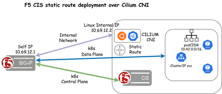
F5 Container Ingress Services (CIS) supports static route configuration to enable direct routing from F5 BIG-IP to Kubernetes/OpenShift Pods as an alternative to VXLAN tunnels. Static routes are enabled in the F5 CIS CLI/Helm yaml manifest using the argument --static-routing-mode=true. In this article, we will use Cilium as the Container Network Interface (CNI) and configure static routes for an NGINX deployment For initial configuration of the BIG-IP, including AS3 installation, please see https://clouddocs.f5.com/products/extensions/f5-appsvcs-extension/latest/userguide/installation.html and https://clouddocs.f5.com/containers/latest/userguide/kubernetes/#cis-installation The first step is to install Cilium CNI using the steps below on Linux host: CILIUM_CLI_VERSION=$(curl -s https://raw.githubusercontent.com/cilium/cilium-cli/main/stable.txt) CLI_ARCH=amd64 if [ "$(uname -m)" = "aarch64" ]; then CLI_ARCH=arm64; fi curl -L --fail --remote-name-all https://github.com/cilium/cilium-cli/releases/download/${CILIUM_CLI_VERSION}/cilium-linux-${CLI_ARCH}.tar.gz{,.sha256sum} sha256sum --check cilium-linux-${CLI_ARCH}.tar.gz.sha256sum sudo tar xzvfC cilium-linux-${CLI_ARCH}.tar.gz /usr/local/bin rm cilium-linux-${CLI_ARCH}.tar.gz{,.sha256sum} cilium install --version 1.18.5 cilium status cilium status --wait root@ciliumk8s-ubuntu-server:~# cilium status --wait /¯¯\ /¯¯\__/¯¯\ Cilium: OK \__/¯¯\__/ Operator: OK /¯¯\__/¯¯\ Envoy DaemonSet: OK \__/¯¯\__/ Hubble Relay: disabled \__/ ClusterMesh: disabled DaemonSet cilium Desired: 1, Ready: 1/1, Available: 1/1 DaemonSet cilium-envoy Desired: 1, Ready: 1/1, Available: 1/1 Deployment cilium-operator Desired: 1, Ready: 1/1, Available: 1/1 Containers: cilium Running: 1 cilium-envoy Running: 1 cilium-operator Running: 1 clustermesh-apiserver hubble-relay Cluster Pods: 6/6 managed by Cilium Helm chart version: 1.18.3 Image versions cilium quay.io/cilium/cilium:v1.18.3@sha256:5649db451c88d928ea585514746d50d91e6210801b300c897283ea319d68de15: 1 cilium-envoy quay.io/cilium/cilium-envoy:v1.34.10-1761014632-c360e8557eb41011dfb5210f8fb53fed6c0b3222@sha256:ca76eb4e9812d114c7f43215a742c00b8bf41200992af0d21b5561d46156fd15: 1 cilium-operator quay.io/cilium/operator-generic:v1.18.3@sha256:b5a0138e1a38e4437c5215257ff4e35373619501f4877dbaf92c89ecfad81797: 1 cilium connectivity test root@ciliumk8s-ubuntu-server:~# cilium connectivity test ℹ️ Monitor aggregation detected, will skip some flow validation steps ✨ [default] Creating namespace cilium-test-1 for connectivity check... ✨ [default] Deploying echo-same-node service... ✨ [default] Deploying DNS test server configmap... ✨ [default] Deploying same-node deployment... ✨ [default] Deploying client deployment... ✨ [default] Deploying client2 deployment... ✨ [default] Deploying ccnp deployment... ⌛ [default] Waiting for deployment cilium-test-1/client to become ready... ⌛ [default] Waiting for deployment cilium-test-1/client2 to become ready... ⌛ [default] Waiting for deployment cilium-test-1/echo-same-node to become ready... ⌛ [default] Waiting for deployment cilium-test-ccnp1/client-ccnp to become ready... ⌛ [default] Waiting for deployment cilium-test-ccnp2/client-ccnp to become ready... ⌛ [default] Waiting for pod cilium-test-1/client-645b68dcf7-s5mdb to reach DNS server on cilium-test-1/echo-same-node-f5b8d454c-qkgq9 pod... ⌛ [default] Waiting for pod cilium-test-1/client2-66475877c6-cw7f5 to reach DNS server on cilium-test-1/echo-same-node-f5b8d454c-qkgq9 pod... ⌛ [default] Waiting for pod cilium-test-1/client-645b68dcf7-s5mdb to reach default/kubernetes service... ⌛ [default] Waiting for pod cilium-test-1/client2-66475877c6-cw7f5 to reach default/kubernetes service... ⌛ [default] Waiting for Service cilium-test-1/echo-same-node to become ready... ⌛ [default] Waiting for Service cilium-test-1/echo-same-node to be synchronized by Cilium pod kube-system/cilium-lxjxf ⌛ [default] Waiting for NodePort 10.69.12.2:32046 (cilium-test-1/echo-same-node) to become ready... 🔭 Enabling Hubble telescope... ⚠️ Unable to contact Hubble Relay, disabling Hubble telescope and flow validation: rpc error: code = Unavailable desc = connection error: desc = "transport: Error while dialing: dial tcp 127.0.0.1:4245: connect: connection refused" ℹ️ Expose Relay locally with: cilium hubble enable cilium hubble port-forward& ℹ️ Cilium version: 1.18.3 🏃[cilium-test-1] Running 126 tests ... [=] [cilium-test-1] Test [no-policies] [1/126] .................... [=] [cilium-test-1] Skipping test [no-policies-from-outside] [2/126] (skipped by condition) [=] [cilium-test-1] Test [no-policies-extra] [3/126] <- snip -> For this article, we will install k3s with Cilium CNI root@ciliumk8s-ubuntu-server:~# curl -sfL https://get.k3s.io | sh -s - --flannel-backend=none --disable-kube-proxy --disable servicelb --disable-network-policy --disable traefik --cluster-init --node-ip=10.69.12.2 --cluster-cidr=10.42.0.0/16 root@ciliumk8s-ubuntu-server:~# mkdir -p $HOME/.kube root@ciliumk8s-ubuntu-server:~# sudo cp -i /etc/rancher/k3s/k3s.yaml $HOME/.kube/config root@ciliumk8s-ubuntu-server:~# sudo chown $(id -u):$(id -g) $HOME/.kube/config root@ciliumk8s-ubuntu-server:~# echo "export KUBECONFIG=$HOME/.kube/config" >> $HOME/.bashrc root@ciliumk8s-ubuntu-server:~# source $HOME/.bashrc API_SERVER_IP=10.69.12.2 API_SERVER_PORT=6443 CLUSTER_ID=1 CLUSTER_NAME=`hostname` POD_CIDR="10.42.0.0/16" root@ciliumk8s-ubuntu-server:~# cilium install --set cluster.id=${CLUSTER_ID} --set cluster.name=${CLUSTER_NAME} --set k8sServiceHost=${API_SERVER_IP} --set k8sServicePort=${API_SERVER_PORT} --set ipam.operator.clusterPoolIPv4PodCIDRList=$POD_CIDR --set kubeProxyReplacement=true --helm-set=operator.replicas=1 root@ciliumk8s-ubuntu-server:~# cilium config view | grep cluster bpf-lb-external-clusterip false cluster-id 1 cluster-name ciliumk8s-ubuntu-server cluster-pool-ipv4-cidr 10.42.0.0/16 cluster-pool-ipv4-mask-size 24 clustermesh-enable-endpoint-sync false clustermesh-enable-mcs-api false ipam cluster-pool max-connected-clusters 255 policy-default-local-cluster false root@ciliumk8s-ubuntu-server:~# cilium status --wait The F5 CIS yaml manifest for deployment using Helm Note that these arguments are required for CIS to leverage static routes static-routing-mode: true orchestration-cni: cilium-k8s We will also be installing custom resources, so this argument is also required 3. custom-resource-mode: true Values yaml manifest for Helm deployment bigip_login_secret: f5-bigip-ctlr-login bigip_secret: create: false username: password: rbac: create: true serviceAccount: # Specifies whether a service account should be created create: true # The name of the service account to use. # If not set and create is true, a name is generated using the fullname template name: k8s-bigip-ctlr # This namespace is where the Controller lives; namespace: kube-system ingressClass: create: true ingressClassName: f5 isDefaultIngressController: true args: # See https://clouddocs.f5.com/containers/latest/userguide/config-parameters.html # NOTE: helm has difficulty with values using `-`; `_` are used for naming # and are replaced with `-` during rendering. # REQUIRED Params bigip_url: X.X.X.S bigip_partition: <BIG-IP_PARTITION> # OPTIONAL PARAMS -- uncomment and provide values for those you wish to use. static-routing-mode: true orchestration-cni: cilium-k8s # verify_interval: # node-poll_interval: # log_level: DEBUG # python_basedir: ~ # VXLAN # openshift_sdn_name: # flannel_name: cilium-vxlan # KUBERNETES # default_ingress_ip: # kubeconfig: # namespaces: ["foo", "bar"] # namespace_label: # node_label_selector: pool_member_type: cluster # resolve_ingress_names: # running_in_cluster: # use_node_internal: # use_secrets: insecure: true custom-resource-mode: true log-as3-response: true as3-validation: true # gtm-bigip-password # gtm-bigip-url # gtm-bigip-username # ipam : true image: # Use the tag to target a specific version of the Controller user: f5networks repo: k8s-bigip-ctlr pullPolicy: Always version: latest # affinity: # nodeAffinity: # requiredDuringSchedulingIgnoredDuringExecution: # nodeSelectorTerms: # - matchExpressions: # - key: kubernetes.io/arch # operator: Exists # securityContext: # runAsUser: 1000 # runAsGroup: 3000 # fsGroup: 2000 # If you want to specify resources, uncomment the following # limits_cpu: 100m # limits_memory: 512Mi # requests_cpu: 100m # requests_memory: 512Mi # Set podSecurityContext for Pod Security Admission and Pod Security Standards # podSecurityContext: # runAsUser: 1000 # runAsGroup: 1000 # privileged: true Installation steps for deploying F5 CIS using helm can be found in this link https://clouddocs.f5.com/containers/latest/userguide/kubernetes/ Once F5 CIS is validated to be up and running, we can now deploy the following application example root@ciliumk8s-ubuntu-server:~# cat application.yaml apiVersion: cis.f5.com/v1 kind: VirtualServer metadata: labels: f5cr: "true" name: goblin-virtual-server namespace: nsgoblin spec: host: goblin.com pools: - path: /green service: svc-nodeport servicePort: 80 - path: /harry service: svc-nodeport servicePort: 80 virtualServerAddress: X.X.X.X --- apiVersion: apps/v1 kind: Deployment metadata: name: goblin-backend namespace: nsgoblin spec: replicas: 2 selector: matchLabels: app: goblin-backend template: metadata: labels: app: goblin-backend spec: containers: - name: goblin-backend image: nginx:latest ports: - containerPort: 80 --- apiVersion: v1 kind: Service metadata: name: svc-nodeport namespace: nsgoblin spec: selector: app: goblin-backend ports: - port: 80 targetPort: 80 type: ClusterIP k apply -f application.yaml We can now verify the k8s pods are created. Then we will create a sample html page to test access to the backend NGINX pod root@ciliumk8s-ubuntu-server:~# k -n nsgoblin get po -owide NAME READY STATUS RESTARTS AGE IP NODE NOMINATED NODE READINESS GATES goblin-backend-7485b6dcdf-d5t48 1/1 Running 0 6d2h 10.42.0.70 ciliumk8s-ubuntu-server <none> <none> goblin-backend-7485b6dcdf-pt7hx 1/1 Running 0 6d2h 10.42.0.97 ciliumk8s-ubuntu-server <none> <none> root@ciliumk8s-ubuntu-server:~# k -n nsgoblin exec -it po/goblin-backend-7485b6dcdf-pt7hx -- /bin/sh # cat > green <<'EOF' <!DOCTYPE html> > > <html> > <head> <title>Green Goblin</title> <style> body { background-color: #4CAF50; color: white; text-align: center; padding: 50px; } h1 { font-size: 3em; } > > > > > </style> </head> <body> <h1>I am the green goblin!</h1> <p>Access me at /green</p> </body> </html> > > > > > > > EOF root@ciliumk8s-ubuntu-server:~# k -n nsgoblin exec -it goblin-backend-7485b6dcdf-d5t48 -- /bin/sh # cat > green <<'EOF' > <!DOCTYPE html> <html> <head> <title>Green Goblin</title> <style> body { background-color: #4CAF50; color: white; text-align: center; padding: 50px; } h1 { font-size: 3em; } </style> > </head> <body> <h1>I am the green goblin!</h1> <p>Access me at /green</p> </body> </html> EOF> > > > > > > > > > > > > We can now validate the pools are created on the F5 BIG-IP root@(ciliumk8s-bigip)(cfg-sync Standalone)(Active)(/kubernetes/Shared)(tmos)# list ltm pool all ltm pool svc_nodeport_80_nsgoblin_goblin_com_green { description "crd_10_69_12_40_80 loadbalances this pool" members { /kubernetes/10.42.0.70:http { address 10.42.0.70 } /kubernetes/10.42.0.97:http { address 10.42.0.97 } } min-active-members 1 partition kubernetes } ltm pool svc_nodeport_80_nsgoblin_goblin_com_harry { description "crd_10_69_12_40_80 loadbalances this pool" members { /kubernetes/10.42.0.70:http { address 10.42.0.70 } /kubernetes/10.42.0.97:http { address 10.42.0.97 } } min-active-members 1 partition kubernetes } root@(ciliumk8s-bigip)(cfg-sync Standalone)(Active)(/kubernetes/Shared)(tmos)# list ltm virtual crd_10_69_12_40_80 ltm virtual crd_10_69_12_40_80 { creation-time 2025-12-22:10:10:37 description Shared destination /kubernetes/10.69.12.40:http ip-protocol tcp last-modified-time 2025-12-22:10:10:37 mask 255.255.255.255 partition kubernetes persist { /Common/cookie { default yes } } policies { crd_10_69_12_40_80_goblin_com_policy { } } profiles { /Common/f5-tcp-progressive { } /Common/http { } } serverssl-use-sni disabled source 0.0.0.0/0 source-address-translation { type automap } translate-address enabled translate-port enabled vs-index 2 } CIS log output 2025/12/22 18:10:25 [INFO] [Request: 1] cluster local requested CREATE in VIRTUALSERVER nsgoblin/goblin-virtual-server 2025/12/22 18:10:25 [INFO] [Request: 1][AS3] creating a new AS3 manifest 2025/12/22 18:10:25 [INFO] [Request: 1][AS3][BigIP] posting request to https://10.69.12.1 for tenants 2025/12/22 18:10:26 [INFO] [Request: 2] cluster local requested UPDATE in ENDPOINTS nsgoblin/svc-nodeport 2025/12/22 18:10:26 [INFO] [Request: 3] cluster local requested UPDATE in ENDPOINTS nsgoblin/svc-nodeport 2025/12/22 18:10:43 [INFO] [Request: 1][AS3][BigIP] post resulted in SUCCESS 2025/12/22 18:10:43 [INFO] [AS3][POST] SUCCESS: code: 200 --- tenant:kubernetes --- message: success 2025/12/22 18:10:43 [INFO] [Request: 3][AS3] Processing request 2025/12/22 18:10:43 [INFO] [Request: 3][AS3] creating a new AS3 manifest 2025/12/22 18:10:43 [INFO] [Request: 3][AS3][BigIP] posting request to https://10.69.12.1 for tenants 2025/12/22 18:10:43 [INFO] Successfully updated status of VirtualServer:nsgoblin/goblin-virtual-server in Cluster W1222 18:10:49.238444 1 warnings.go:70] v1 Endpoints is deprecated in v1.33+; use discovery.k8s.io/v1 EndpointSlice 2025/12/22 18:10:52 [INFO] [Request: 3][AS3][BigIP] post resulted in SUCCESS 2025/12/22 18:10:52 [INFO] [AS3][POST] SUCCESS: code: 200 --- tenant:kubernetes --- message: success 2025/12/22 18:10:52 [INFO] Successfully updated status of VirtualServer:nsgoblin/goblin-virtual-server in Cluster Troubleshooting: 1. If static routes are not added, the first step is to inspect CIS logs for entries similar to these: Cilium annotation warning logs 2025/12/22 17:44:45 [WARNING] Cilium node podCIDR annotation not found on node ciliumk8s-ubuntu-server, node has spec.podCIDR ? 2025/12/22 17:46:41 [WARNING] Cilium node podCIDR annotation not found on node ciliumk8s-ubuntu-server, node has spec.podCIDR ? 2025/12/22 17:46:42 [WARNING] Cilium node podCIDR annotation not found on node ciliumk8s-ubuntu-server, node has spec.podCIDR ? 2025/12/22 17:46:43 [WARNING] Cilium node podCIDR annotation not found on node ciliumk8s-ubuntu-server, node has spec.podCIDR ? 2. These are resolved by adding annotations to the node using the reference: https://clouddocs.f5.com/containers/latest/userguide/static-route-support.html Cilium annotation for node root@ciliumk8s-ubuntu-server:~# k annotate node ciliumk8s-ubuntu-server io.cilium.network.ipv4-pod-cidr=10.42.0.0/16 root@ciliumk8s-ubuntu-server:~# k describe node | grep -E "Annotations:|PodCIDR:|^\s+.*pod-cidr" Annotations: alpha.kubernetes.io/provided-node-ip: 10.69.12.2 io.cilium.network.ipv4-pod-cidr: 10.42.0.0/16 PodCIDR: 10.42.0.0/24 3. Verify a static route has been created and test connectivity to k8s pods root@(ciliumk8s-bigip)(cfg-sync Standalone)(Active)(/kubernetes)(tmos)# list net route net route k8s-ciliumk8s-ubuntu-server-10.69.12.2 { description 10.69.12.1 gw 10.69.12.2 network 10.42.0.0/16 partition kubernetes } Using pup (command line HTML parser) -> https://commandmasters.com/commands/pup-common/ root@ciliumk8s-ubuntu-server:~# curl -s http://goblin.com/green | pup 'body text{}' I am the green goblin! Access me at /green 1 0.000000 10.69.12.34 ? 10.69.12.40 TCP 78 34294 ? 80 [SYN] Seq=0 Win=64240 Len=0 MSS=1460 SACK_PERM TSval=2984295232 TSecr=0 WS=128 2 0.000045 10.69.12.40 ? 10.69.12.34 TCP 78 80 ? 34294 [SYN, ACK] Seq=0 Ack=1 Win=23360 Len=0 MSS=1460 WS=512 SACK_PERM TSval=1809316303 TSecr=2984295232 3 0.001134 10.69.12.34 ? 10.69.12.40 TCP 70 34294 ? 80 [ACK] Seq=1 Ack=1 Win=64256 Len=0 TSval=2984295234 TSecr=1809316303 4 0.001151 10.69.12.34 ? 10.69.12.40 HTTP 149 GET /green HTTP/1.1 5 0.001343 10.69.12.40 ? 10.69.12.34 TCP 70 80 ? 34294 [ACK] Seq=1 Ack=80 Win=23040 Len=0 TSval=1809316304 TSecr=2984295234 6 0.002497 10.69.12.1 ? 10.42.0.97 TCP 78 33707 ? 80 [SYN] Seq=0 Win=23360 Len=0 MSS=1460 WS=512 SACK_PERM TSval=1809316304 TSecr=0 7 0.003614 10.42.0.97 ? 10.69.12.1 TCP 78 80 ? 33707 [SYN, ACK] Seq=0 Ack=1 Win=64308 Len=0 MSS=1410 SACK_PERM TSval=1012609408 TSecr=1809316304 WS=128 8 0.003636 10.69.12.1 ? 10.42.0.97 TCP 70 33707 ? 80 [ACK] Seq=1 Ack=1 Win=23040 Len=0 TSval=1809316307 TSecr=1012609408 9 0.003680 10.69.12.1 ? 10.42.0.97 HTTP 149 GET /green HTTP/1.1 10 0.004774 10.42.0.97 ? 10.69.12.1 TCP 70 80 ? 33707 [ACK] Seq=1 Ack=80 Win=64256 Len=0 TSval=1012609409 TSecr=1809316307 11 0.004790 10.42.0.97 ? 10.69.12.1 TCP 323 HTTP/1.1 200 OK [TCP segment of a reassembled PDU] 12 0.004796 10.42.0.97 ? 10.69.12.1 HTTP 384 HTTP/1.1 200 OK 13 0.004820 10.69.12.40 ? 10.69.12.34 TCP 448 HTTP/1.1 200 OK [TCP segment of a reassembled PDU] 14 0.004838 10.69.12.1 ? 10.42.0.97 TCP 70 33707 ? 80 [ACK] Seq=80 Ack=254 Win=23552 Len=0 TSval=1809316308 TSecr=1012609410 15 0.004854 10.69.12.40 ? 10.69.12.34 HTTP 384 HTTP/1.1 200 OK Summary: There we have it, we have successfully deployed an NGINX application on a Kubernetes cluster managed by F5 CIS using static routes to forward traffic to the kubernetes pods973Views3likes2CommentsThe Ingress NGINX Alternative: F5 NGINX Ingress Controller for the Long Term
The Kubernetes community recently announced that Ingress NGINX will be retired in March 2026. After that date, there won’t be any more new updates, bugfixes, or security patches. ingress-nginx is no longer a viable enterprise solution for the long-term, and organizations using it in production should move quickly to explore alternatives and plan to shift their workloads to Kubernetes ingress solutions that are continuing development. Your Options (And Why We Hope You’ll Consider NGINX) There are several good Ingress controllers available—Traefik, HAProxy, Kong, Envoy-based options, and Gateway API implementations. The Kubernetes docs list many of them, and they all have their strengths. Security start-up Chainguard is maintaining a status-quo version of ingress-nginx and applying basic safety patches as part of their EmeritOSS program. But this program is designed as a stopgap to keep users safe while they transition to a different ingress solution. F5 maintains an OSS permissively licensed NGINX Ingress Controller. The project is open source, Apache 2.0 licensed, and will stay that way. There is a team of dedicated engineers working on it with a slate of upcoming upgrades. If you’re already comfortable with NGINX and just want something that works without a significant learning curve, we believe that the F5 NGINX Ingress Controller for Kubernetes is your smoothest path forward. The benefits of adopting NGINX Ingress Controller open source include: Genuinely open source: Apache 2.0 licensed with 150+ contributors from diverse organizations, not just F5. All development happens publicly on GitHub, and F5 has committed to keeping it open source forever. Plus community calls every 2 weeks. Minimal learning curve: Uses the same NGINX engine you already know. Most Ingress NGINX annotations have direct equivalents, and the migration guide provides clear mappings for your existing configurations. Supported annotations include popular ones such as nginx.org/client-body-buffer-size mirrors nginx.ingress.kubernetes.io/client-body-buffer-size (sets the maximum size of the client request body buffer). Also available in VirtualServer and ConfigMap. nginx.org/rewrite-target mirrors nginx.ingress.kubernetes.io/rewrite-target (sets a replacement path for URI rewrites) nginx.org/ssl-ciphers mirrors nginx.ingress.kubernetes.io/ssl-ciphers (configures enabled TLS cipher suites) nginx.org/ssl-prefer-server-cipher mirrors nginx.ingress.kubernetes.io/ssl-prefer-server-ciphers (controls server-side cipher preference during the TLS handshake) Optional enterprise-grade capabilities: While the OSS version is robust, NGINX Plus integration is available for enterprises needing high availability, authentication and authorization, session persistence, advanced security and commercial support Sustainable maintenance: A dedicated full-time team at F5 ensures regular security updates, bug fixes, and feature development. Production-tested at scale: NGINX Ingress Controller powers approximately 40% of Kubernetes Ingress deployments with over 10 million downloads. It’s battle-tested in real production environments. Kubernetes-native design: Custom Resource Definitions (VirtualServer, Policy, TransportServer) provide cleaner configuration than annotation overload, with built-in validation to prevent errors. Advanced capabilities when you need them: Support for canary deployments, A/B testing, traffic splitting, JWT validation, rate limiting, mTLS, and more—available in the open source version. Future-proof architecture: Active development of NGINX Gateway Fabric provides a clear migration path when you’re ready to move to Gateway API. NGINX Gateway Fabric is a conformant Gateway API solution under CNCF conformance criteria and it is one of the most widely used open source Gateway API solutions. Moving to NGINX Ingress Controller Here’s a rough migration guide. You can also check our more detailed migration guide on our documentation site. Phase 1: Take Stock See what you have: Document your current Ingress resources, annotations, and ConfigMaps Check for snippets: Identify any annotations like: nginx.ingress.kubernetes.io/configuration-snippet Confirm you're using it: Run kubectl get pods --all-namespaces --selector app.kubernetes.io/name=ingress-nginx Set it up alongside: Install NGINX Ingress Controller in a separate namespace while keeping your current setup running Phase 2: Translate Your Config Convert annotations: Most of your existing annotations have equivalents in NGINX Ingress Controller - there's a comprehensive migration guide that maps them out Consider VirtualServer resources: These custom resources are cleaner than annotation-heavy Ingress, and give you more control, but it's your choice Or keep using Ingress: If you want minimal changes, it works fine with standard Kubernetes Ingress resources Handle edge cases: For anything that doesn't map directly, you can use snippets or Policy resources Phase 3: Test Everything Try it with test apps: Create some test Ingress rules pointing to NGINX Ingress Controller Run both side-by-side: Keep both controllers running and route test traffic through the new one Verify functionality: Check routing, SSL, rate limiting, CORS, auth—whatever you're using Check performance: Verify it handles your traffic the way you need Phase 4: Move Over Gradually Start small: Migrate your less-critical applications first Shift traffic slowly: Update DNS/routing bit by bit Watch closely: Keep an eye on logs and metrics as you go Keep an escape hatch: Make sure you can roll back if something goes wrong Phase 5: Finish Up Complete the migration: Move your remaining workloads Clean up the old controller: Uninstall community Ingress NGINX once everything's moved Tidy up: Remove old ConfigMaps and resources you don't need anymore Enterprise-grade capabilities and support Once an ingress layer becomes mission-critical, enterprise features become necessary. High availability, predictable failover, and supportability matter as much as features. Enterprise-grade capabilities available for NGINX Ingress Controller Plus include high availability, authentication and authorization, commercial support, and more. These ensure production traffic remains fast, secure, and reliable. Capabilities include: Commercial support Backed by vendor commercial support (SLAs, escalation paths) for production incidents Access to tested releases, patches, and security fixes suitable for regulated/enterprise environments Guidance for production architecture (HA patterns, upgrade strategies, performance tuning) Helps organizations standardize on a supported ingress layer for platform engineering at scale Dynamic Reconfiguration Upstream configuration updates via API without process reloads Eliminates memory bloat and connection timeouts as upstream server lists and variables are updated in real time when pods scale or configurations change Authentication & Authorization Built-in authentication support for OAuth 2.0 / OIDC, JWT validation, and basic auth External identity provider integration (e.g., Okta, Azure AD, Keycloak) via auth request patterns JWT validation at the edge, including signature verification, claims inspection, and token expiry enforcement Fine-grained access control based on headers, claims, paths, methods, or user identity Optional Web Application Firewall Native integration with F5 WAF for NGINX for OWASP Top 10 protection, gRPC schema validation, and OpenAPI enforcement DDoS mitigation capabilities when combined with F5 security solutions Centralized policy enforcement across multiple ingress resources High availability (HA) Designed to run as multiple Ingress Controller replicas in Kubernetes for redundancy and scale State sharing: Maintains session persistence, rate limits, and key-value stores for seamless uptime. Here’s the full list of differences between NGINX Open Source and NGINX One – a package that includes NGINX Plus Ingress Controller, NGINX Gateway Fabric, F5 WAF for NGINX, and NGINX One Console for managing NGINX Plus Ingress Controllers at scale. Get Started Today Ready to begin your migration? Here's what you need: 📚 Read the full documentation: NGINX Ingress Controller Docs 💻 Clone the repository: github.com/nginx/kubernetes-ingress 🐳 Pull the image: Docker Hub - nginx/nginx-ingress 🔄 Follow the migration guide: Migrate from Ingress-NGINX to NGINX Ingress Controller Interested in the enterprise version? Try NGINX One for free and give it a whirl The NGINX Ingress Controller community is responsive and full of passionate builders -- join the conversation in the GitHub Discussions or the NGINX Community Forum. You’ve got time to plan this migration right, but don’t wait until March 2026 to start.2.4KViews1like0CommentsF5 Distributed Cloud Kubernetes Integration: Securing Services with Direct Pod Connectivity
Introduction As organizations embrace Kubernetes for container orchestration, they face critical challenges in exposing services securely to external consumers while maintaining granular control over traffic management and security policies. Traditional approaches using NodePort services or basic ingress controllers often fall short in providing the advanced application delivery and security features required for production workloads. F5 Distributed Cloud (F5 XC) addresses these challenges by offering enterprise-grade application delivery and security services through its Customer Edge (CE) nodes. By establishing direct connectivity to Kubernetes pods, F5 XC can provide sophisticated load balancing, WAF protection, API security, and multi-cloud connectivity without the limitations of NodePort-based architectures. This article demonstrates how to architect and implement F5 XC CE integration with Kubernetes clusters to expose and secure services effectively, covering both managed Kubernetes platforms (AWS EKS, Azure AKS, Google GKE) and self-managed clusters using K3S with Cilium CNI. Understanding F5 XC Kubernetes Service Discovery F5 Distributed Cloud includes a native Kubernetes service discovery feature that communicates directly with Kubernetes API servers to retrieve information about services and their associated pods. This capability operates in two distinct modes: Isolated Mode In this mode, F5 XC CE nodes are isolated from the Kubernetes cluster pods and can only reach services exposed as NodePort services. While the discovery mechanism can retrieve all services, connectivity is limited to NodePort-exposed endpoints with the inherent NodePort limitations: Port Range Restrictions: Limited to ports 30000-32767 Security Concerns: Exposes services on all node IPs Performance Overhead: Additional network hops through kube-proxy Limited Load Balancing: Basic round-robin without advanced health checks Non-Isolated Mode, Direct Pod Connectivity (and why it matters) This is the focus of our implementation. In non-isolated mode, F5 XC CE nodes can reach Kubernetes pods directly using their pod IP addresses. This provides several advantages: Simplified Architecture: Eliminate NodePort complexity and port management limitation Enhanced Security: Apply WAF, DDoS protection, and API security directly at the pod level Advanced Load Balancing: Sophisticated algorithms, circuit breaking, and retry logic Architectural Patterns for Pod IP Accessibility To enable direct pod connectivity from external components like F5 XC CEs, the pod IP addresses must be routable outside the Kubernetes cluster. The implementation approach varies based on your infrastructure: Cloud Provider Managed Kubernetes Cloud providers typically handle pod IP routing through their native Container Network Interfaces (CNIs): Figure 1: Cloud providers' K8S CNI routes PODs IPs to the Cloud Provider Private Cloud Routing Table AWS EKS: Uses Amazon VPC CNI, which assigns VPC IP addresses directly to pods Azure AKS: Traditional CNI mode allocates Azure VNET IPs to pods Google GKE: VPC-native clusters provide direct pod IP routing In these environments, the cloud provider's CNI automatically updates routing tables to make pod IPs accessible within the VPC/VNET. Self-Managed Kubernetes Clusters For self-managed clusters, you need an advanced CNI that can expose the Kubernetes overlay network. The most common solutions are: Cilium: Provides eBPF-based networking with BGP support Calico: Offers flexible networking policies with BGP peering capabilities and eBPF support as well These CNIs typically use BGP to advertise pod subnets to external routers, making them accessible from outside the cluster. Figure 2: Self-managed K8S clusters use advanced CNI with BGP to expose the overlay subnet Cloud Provider Implementations AWS EKS Architecture Figure 3: AWS EKS with F5 XC CE integration using VPC CNI With AWS EKS, the VPC CNI plugin assigns real VPC IP addresses to pods, making them directly routable within the VPC without additional configuration. Azure AKS Traditional CNI Figure 4: Azure AKS with traditional CNI mode for direct pod connectivity Azure's traditional CNI mode allocates IP addresses from the VNET subnet directly to pods, enabling native Azure networking features. Google GKE VPC-Native Figure 5: Google GKE VPC-native clusters with alias IP ranges for pods GKE's VPC-native mode uses alias IP ranges to provide pods with routable IP addresses within the Google Cloud VPC. Deeper dive into the implementation Implementation Example 1: AWS EKS Integration Let's walk through a complete implementation using AWS EKS as our Kubernetes platform. Prerequisites and Architecture Network Configuration: VPC CIDR: 10.154.0.0/16 Three private subnets (one per availability zone) F5 XC CE deployed in Private Subnet 1 EKS worker nodes distributed across all three subnets Figure 6: Complete EKS implementation architecture with F5 XC CE integration Kubernetes Configuration: EKS cluster with AWS VPC CNI Sample application: microbot (simple HTTP service) Three replicas distributed across nodes What is running inside the K8S cluster? The PODs We have three PODs in the default namespace. Figure 7: The running PODs in the EKS cluster One running with POD IP 10.154.125.116, another one with POD IP 10.154.76.183 and one running with POD IP 10.154.69.183. microbot POD is a simple HTTP application that is returning the full name of the POD and an image. Figure 8: The microbot app The services Figure 9: The services running in the EKS cluster Configure F5 XC Kubernetes Service Discovery Create a K8S service discovery object. Figure 10: Kubernetes service discovery configuration In the “Access Credentials” activate the “Show Advanced Fields” slider. This is the key! Figure 11: The "advanced fields" slider Then provide the Kubeconfig file of the K8S cluster and select “Kubernetes POD reachable”. Figure 12: Kubernetes POD network reachability Then the K8S should be displayed in the “Service Discoveries”. Figure 13: The discovered PODs IPs One can see that the services are discovered by the F5 XC node and more interestingly, the PODs IPs. Are the pods reachable from the F5XC CE? Figure 14: Testing connectivity to pod 10.154.125.116 Figure 15: Testing connectivity to pod 10.154.76.183 Figure 16: Testing connectivity to pod 10.154.69.183 Yes, they are! Create Origin Pool with K8S Service Create an origin pool that references your Kubernetes service: Figure 17: Creating origin pool with Kubernetes service type Create an HTTPS Load-Balancer and test the service Just create a regular F5 XC HTTPS Load-Balancer and use the origin pool created above. Figure 18: Traffic load-balanced across the three PODs The result shows traffic being load-balanced across all EKS pods. Implementation Example 2: Self-Managed K3S with Cilium CNI One infrastructure subnet (10.154.1.0/24) in which the following components are going to be deployed: F5 XC CE single node (10.154.1.100) Two Linux Ubuntu nodes (10.154.1.10 & 10.154.1.11) On the Linux Ubuntu nodes, a Kubernetes cluster is going to be deployed using K3S (www.k3s.io) with the following specifications: PODs overlay subnet: 10.160.0.0/16 Services overlay subnet: 10.161.0.0/16 Default K3S CNI (flannel) will be disabled K3S CNI will be replaced by Cilium CNI to expose directly the PODs overlay subnet to the “external world” Figure 19: Self-managed K3S cluster with Cilium CNI and BGP peering to F5 XC CE What is running inside the K8S cluster? The PODs We have two PODs in the default namespace. Figure 20: The running PODs in the K8S cluster One running on node “k3s-1” with POD IP 10.160.0.203 and the other one running on node “k3s-2” with POD IP 10.160.1.208. microbot POD is a simple HTTP application that is returning the full name of the POD and an image. The services Figure 21: The services running in the K8S cluster Different Kubernetes services are created to expose the microbot PODs, one of type Cluster IP and the other one of type LoadBalancer. The type of service doesn’t really matter for F5XC because we are working in a full routed mode between the CE and the K8S cluster. F5XC only needs to “know” the PODs IPs, which will be discovered through the services. Configure F5 XC Kubernetes Service Discovery Steps are identical regarding what we did for EKS. And once done, services and PODs IPs are discovered by F5XC. Figure 22: The discovered PODs IPs Configure the BGP peering on F5XC CE In this example topology, BGP peerings are established directly between the K8S nodes and the F5 XC CE. Other implementations are possible, for instance, with an intermediate router. Figure 23: BGP peerings Check if the peerings are established. Figure 24: Verification of the BGP peerings Are the pods reachable from the F5XC CE? Figure 25: PODs reachability test They are! Create Origin Pool with K8S Service As we did for the EKS configuration, create an origin pool that references your Kubernetes service. Create an HTTPS Load-Balancer and test the service Just create a regular F5 XC HTTPS Load-Balancer and use the origin pool created above. Figure 26: Traffic load-balanced across the two PODs Scaling up? Let’s add another POD to the deployment to see how F5XC will handle the load-balancing after. Figure 27: Scaling up the Microbot PODs And it’s working! Load is spread automatically as soon as new PODs instances are available for the given service. Figure 28: Traffic load-balanced across the three PODs Appendix - K3S and Cilium deployment example Step 1: Install K3S without Default CNI On the master node: curl -sfL https://get.k3s.io | K3S_KUBECONFIG_MODE="644" \ INSTALL_K3S_EXEC="--flannel-backend=none \ --disable-network-policy \ --disable=traefik \ --disable servicelb \ --cluster-cidr=10.160.0.0/16 \ --service-cidr=10.161.0.0/16" sh - # Export kubeconfig export KUBECONFIG=/etc/rancher/k3s/k3s.yaml # Get token for worker nodes sudo cat /var/lib/rancher/k3s/server/node-token On worker nodes: IP_MASTER=10.154.1.10 K3S_TOKEN=<token-from-master> curl -sfL https://get.k3s.io | K3S_URL=https://${IP_MASTER}:6443 K3S_TOKEN=${K3S_TOKEN} sh - Step 2: Install and Configure Cilium On the K3S master node, please perform the following: Install Helm and Cilium CLI: # Install Helm sudo snap install helm --classic # Download Cilium CLI CILIUM_CLI_VERSION=$(curl -s https://raw.githubusercontent.com/cilium/cilium-cli/main/stable.txt) CLI_ARCH=amd64 curl -L --fail --remote-name-all https://github.com/cilium/cilium-cli/releases/download/${CILIUM_CLI_VERSION}/cilium-linux-${CLI_ARCH}.tar.gz{,.sha256sum} sha256sum --check cilium-linux-${CLI_ARCH}.tar.gz.sha256sum sudo tar xzvfC cilium-linux-${CLI_ARCH}.tar.gz /usr/local/bin Install Cilium with BGP support: helm repo add cilium https://helm.cilium.io/ helm install cilium cilium/cilium --version 1.16.5 \ --set=ipam.operator.clusterPoolIPv4PodCIDRList="10.160.0.0/16" \ --set kubeProxyReplacement=true \ --set k8sServiceHost=10.154.1.10 \ --set k8sServicePort=6443 \ --set bgpControlPlane.enabled=true \ --namespace kube-system \ --set bpf.hostLegacyRouting=false \ --set bpf.masquerade=true # Monitor installation cilium status --wait Step 3: Configure BGP Peering Label nodes for BGP: kubectl label nodes k3s-1 bgp=true kubectl label nodes k3s-2 bgp=true Create BGP configuration: # BGP Cluster Config apiVersion: cilium.io/v2alpha1 kind: CiliumBGPClusterConfig metadata: name: cilium-bgp spec: nodeSelector: matchLabels: bgp: "true" bgpInstances: - name: "k3s-instance" localASN: 65001 peers: - name: "f5xc-ce" peerASN: 65002 peerAddress: 10.154.1.100 peerConfigRef: name: "cilium-peer" --- # BGP Peer Config apiVersion: cilium.io/v2alpha1 kind: CiliumBGPPeerConfig metadata: name: cilium-peer spec: timers: holdTimeSeconds: 9 keepAliveTimeSeconds: 3 gracefulRestart: enabled: true restartTimeSeconds: 15 families: - afi: ipv4 safi: unicast advertisements: matchLabels: advertise: "bgp" --- # BGP Advertisement apiVersion: cilium.io/v2alpha1 kind: CiliumBGPAdvertisement metadata: name: bgp-advertisements labels: advertise: bgp spec: advertisements: - advertisementType: "PodCIDR"871Views3likes1Comment