dns
134 Topics
Building digital resilience to enable digital sovereignty
In 2025, cloud service outages significantly impacted enterprises worldwide, prompting urgent calls for improved digital resilience and sovereignty strategies. Organizations face regulatory pressures and costly disruptions, necessitating robust approaches to maintain continuity and trust in critical infrastructure sectors. Digital resilience defined: Digital resilience is the capability of an organization to prevent, detect, respond to, and recover from infrastructure failures or cyberattacks, including those originating externally, making it essential for modern business continuity. Frameworks guiding resilience: Key regulatory and industry frameworks such as NIST Cybersecurity Framework, ISO/IEC 27001, COBIT, ITIL, BCM, DORA, and APRA CPS 230 provide structured guidance on managing cybersecurity, operational resilience, and third-party risk, forming the governance foundation for resilience strategies. Strategies for resilience: Effective digital resilience involves mapping applications to appropriate deployment models like distributed and redundant deployments, implementing intelligent traffic management, adaptive security, network segmentation, automation with failover testing, and continuous monitoring through visibility and analytics. Resilience and digital sovereignty: Digital resilience intersects with emerging digital sovereignty requirements that emphasize data location and governance. Achieving combined goals involves antifragile architectures that limit disruption impact, adapt to threats, and improve through learning, supported by F5 ADSP.382Views1like1CommentMinIO AIStor and F5 BIG-IP DNS – Globally steer and replicate your S3 object storage
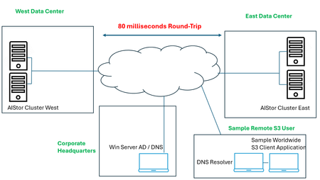
A set of two complementary technologies were set out to be assessed, the first being MinIO’s active-active replication, which serves to keep buckets in sync across wide areas. This is more than object copying. It fully includes replication of delete operations, delete markers, existing objects, and replica metadata changes. As discussed in this blog, the ability exists to configure this across two or more sites, in interesting approaches like two data centers in one metro market all the way to a larger set spanning a continent; all are in play. As the blog indicates, the deliverable solution can be for multi-primary topologies, fast hot-hot failover, and multi-geo resiliency. The second technology, F5 BIG-IP DNS and LTM modules, can impose control over the path to these active-active scenarios. The ambitious requirements surrounding global server load balancing (or GSLB, for short) is directly in BIG-IP’s wheelhouse. The fully qualified domain names (FQDN) of vast sets of S3 buckets can now be put under the purview of BIG-IP. S3 users might be delivered to data centers filled with MinIO AIStor clusters using a simple round-robin approach, or perhaps a strategy where one data center is considered live, while another is ready for a hot standby switchover, in the event that network impairments arise. This is only the start of the possibilities. What about a strategy where topological knowledge is unleashed, say American users in the Atlanta region are steered to an east coast MinIO data center, say New York City, while all bucket data is immediately then synchronized to a west coast data center, perhaps in Los Angeles? A lab setup for learning All of the geographic traffic steering capabilities can become a rabbit hole, the only limiting factor is often the imagination of the solution architect. Take one final suggested and sequenced approach, first topology is used based upon the source addresses of incoming DNS queries. The idea could be to steer user traffic to “pools” of data centers on a continental -basis: traffic from users in North America is first filtered to a North American picklist of sites, Europeans to EMEA locations, perhaps Asian users to Asia Pac data centers. Things then get really interesting at the next layer, although again topology can be leaned on, BIG-IP DNS can also be instructed to slowly poll users’ local DNS resolvers over time, such that future requests for service from, say, Atlanta as an example, again, would receive a solution which knows that the round-trip response times from New York are actually and demonstrably quicker than Los Angeles and result in that being the first criteria used to steer S3 to its optimal data center cluster. The following was the objective of the lab’s setup, a two cluster AIStor solution, multiple 4-disk AIStors in each data center’s cluster. Although replication can be synchronous or asynchronous, the latter is a better fit in cases where distance between participating data centers is significant. To introduce latency reflective of North American coast-to-coast normal values, WAN latency was emulated in the lab and an asynchronous replication between buckets was selected. A key take away from the diagram is the administration component, the so called “Corporate Headquarters” and the fact that it is not collocated with storage. It does however, have authoritative control over DNS domains in use. Also, note the sample S3 consumers may be located anywhere, and latency to each data center will be unique. The MinIO AIStor active-active setup in a nutshell The MinIO blog post referenced earlier takes a user through an easy-to-follow GUI-based approach to setting up the clusters for replication, however the command-line mcli approach is also valid. The MinIO documentation site can be found here and covers the replication topic in general. The key takeaways for anyone standing up an environment like that described in this article: The bare minimum for erasure coding, a foundational part of MinIO’s data resiliency story, is 4 drives. I have used 2 servers with 4 drives, for 8 drives, per site. Ample bandwidth between sites, in my lab I have 100 Mbps between emulated sites. Buckets to be included in an active-active replication approach must have both versioning and object-locking enabled when creating them, matching identical buckets and permissions should be set up at all other participating data centers. In this lab setup, the fictious organization is byteboutique.io, a distributed organization with MinIO storage in multiple locations, allowing B2B partners to access via S3 buckets line of business material such as “datasheets”, “product-videos” and “sales-orders-inventory”. When creating the buckets with the AIStor GUI, such as for a new bucket “sales-reports”, simply ensure versioning and object-lock are requested. Versioning allows objects touched at one location to be kept in sync with the versions accessible at all locations, even deleted objects are simply versioned and retained under the hood for future usage. Once this is performed at the clusters in each participating site, the next step is quite straightforward. Simply group select the buckets in question and feed AIStor the information about the desired replication. The last step, after pressing the button above, is to set up the replication parameters to initiate communications with the other AIStor site in the lab. At this point, objects delivered into either site’s buckets, using perhaps graphical tools like S3browser, will be replicated to the same bucket in other data centers. The next requirement is how can we use the F5 technology to provide a universal naming convention, as both humans and business automated routines prefer DNS names over static IP addresses. We want an S3 application to write to byteboutique.io’s buckets with knowledge that the content will go to one MinIO site, any site. It could even be done in a round-robin manner. The beauty of the active-active angle is that the automated backend replication work is shielded from the user. Beyond this, we can take things one step further and have the BIG-IP use context such as source IP awareness or on-going network response measurements to guide that S3 traffic to the best possible landing site. Global load balancing S3 traffic with BIG-IP DNS and LTM – infrastructure setup We can adjust our diagram to introduce the two F5 components required to meet the lab objectives. Each emulated data center will have one BIG-IP, as a minimum these appliances will have the local traffic manager (LTM) module licensed. LTM allows incoming S3 transactions to be load balanced per selected algorithm to AIStor nodes local to that site. The “least connections” algorithm is a popular choice for heavy S3 traffic flow. The received S3 traffic will be both new, user-initiated requests as well as traffic generated by AIStor clusters themselves to achieve a perpetually replicated state amongst sites. The other component to be licensed is the DNS module. This will allow global traffic steering and need not be on all BIG-IP appliances. It can co-habitate nicely with the LTM module, so perhaps some data center-housed BIG-IPs will use it, as well as BIG-IP appliances that might already exist in other areas, such as in a corporate headquarters. The minimum number of BIG-IP DNS appliances is two, but for production more would be recommended. In our lab setup, the headquarters Windows server is the authoritative DNS server for our fictious byteboutique.io domain. What we can quickly do is delegate control over the sub-domain corp.byteboutique.io to our BIG-IP DNS appliances. In other words, we will create DNS Name Server (NS) resource records for the “corp” sub-domain which point to the BIG-IPs. This is the critical cog in the wheel. All S3 accessible buckets will use DNS names below corp and are thus fully under the control of the BIG-IP administrator. Other approaches that can retain existing domain names and put them under the control of BIG-IP DNS would include using CNAME DNS resource records. In the following image, we see that the delegated corp domain has NS resource records added, and that looking at the main byteboutique.io resource records, there are A resource records pointing to IP addresses dedicated to DNS on both the HQ and East data center BIG-IPs (30.0.0.12 and 40.0.0.12). We are halfway home. Now we just need to see the key parameters of a BIG-IP DNS configuration. There is both regular F5 documentation on the DNS solution here and also a very handy lab guide here that graphically provides every step towards a sample classroom set up. To simply hit on the main tasks, the BIG-IP DNS appliances must be set to join a common DNS “group”, the name “F5DEMO_group” is used in the following lab setup screenshot. This means BIG-IPs in the DNS group can share content like zone files and collectively control where S3 traffic lands. The impactful part to you? After joining the BIG-IP DNS appliances with the “gtm_add” command, you will only ever need to create new FQDN values (such as an S3 service at name storage.corp.byteboutique.io) on just one BIG-IP DNS and all others in the group will be adjusted accordingly behind the scenes. Phew. So, with DNS administration, just set it and forget it on any BIG-IP member of your choice. Beneath the surface, F5’s iQuery protocol is in play to keep DNS members coordinated automatically. The only other command-line task in this whole endeavor is to issue “bigip_add” at each appliance, LTM, DNS, or LTM/DNS. This will let the device’s certificates be trusted by other appliance peers and allow secure communications between each. The next task is to create logical holding entities for our locations, simply and intuitively called “Data Centers”. As such, we will need entries for our diagram’s east site, west site, and headquarters. The last step of this one-time infrastructure setup phase is to add “servers” at each site. These correspond to all BIG-IP appliances, including LTM only appliances, which serve to load balance to AIStor nodes. The nice part, you ask? A discovery feature includes all the currently configured virtual servers at each site, so the task is simply adding to the server list and choosing a health check to be run in the background. Here is our server list. Notice the virtual server count has been populated, including the hq site which being licensed only for the DNS module, understandably has no virtual servers. Tying it all together - modern traffic steering for MinIO S3 buckets with F5 BIG-IP Before answering the age-old question, what precisely is a “Wide IP” anyways, let us settle on some term clarity first. For anyone with a background in BIG-IP LTM, or any on-prem load balancer, a pool normally means a set of local origin servers “behind” the load balancer. These might be Linux appliances with Nginx webservers, Windows-based server applications based around IIS, or in our case, MinIO AIStor servers offering S3 API-compatible object storage services. In the world of GSLB there are actually two tiers of pools, the first tier of pool allows groups of data centers, not individual origin servers, to be selected by one of the many available algorithms. Consider this as an example, when first selecting a pool for a mock web application, named myapp.global.example.com. In the above example, created purely for illustration, incoming requests for the domain name myapp.global.example.com would be round robin directed to either data centers in the Americas, or Asia or Europe regions. In reality, a topology-based load balancing method, not round robin, would likely be invoked in the top “Load Balancing Method” pull down. The key point is to highlight that each region might have a half dozen data centers, or more, each equipped with BIG-IP virtual servers ready to handle application traffic delivered there. This is a very reasonable first pool-level approach you might use, and the FQDN in the example (myapp.global.example.com) is referred to as a “Wide IP”. A Wide IP, or WIP for short, is an F5 DNS construct that maps names to pools first, and then to individual sites (housing virtual servers) second. In our lab, our Wide IP to get S3 transactions to MinIO AIStor nodes, is “storage.corp.byteboutique.io”. We can see we have just one pool, as denoted by the arrow. Perhaps think of this as a North America-only scenario, but a solution that is ready to be rolled out internationally when byteboutique really takes off and expands to the world. Drilling down by clicking on our WIP, we see the one pool, and observe two “members”, meaning two virtual servers are associated to this pool. This is a quick shorthand count of sorts, we know we are looking at a solution where the WIP resolves to one of two possible MinIO-equipped data centers. Interestingly, since our lab is using one pool, the actual load balancing method at this layer is moot. Round robin is seen in the above screenshot however any other mechanism of selecting from a pool set of one will, of course, not be impactful. However, by clicking onto the pool itself, we get to the heart of the actual decision-making logic in our lab setup. The following screen will dictate what IP address, meaning what site’s S3 virtual server IP address, will be delivered to a client’s local DNS resolver upon request (double-click to enlarge). We see that the two sites of our lab, east and west, are both represented in the virtual server “Member” list of our pool. The status is green, as both virtual servers are, within the two respective data centers, evaluating perpetually that the AIStor servers for in good (green) health. This is a subtle but powerful feature of BIG-IP GSLB versus normal DNS, we can see “behind” the load balancer in our two sites and ensure traffic will never be sent to a site that is having issues communicating with a sufficient number of backend S3 nodes. Perhaps you will want to think of this as "intelligent" DNS. The other major takeaway is the load balancing logic. This is a simple, perhaps “fast start” approach. We are using a static round-robin algorithm, when DNS A resource record (RR) requests are delivered to either BIG-IP DNS appliance, since they are authoritative for *.corp.byteboutique.io, the IPs of the two virtual servers will be utilized in responses, in a round robin manner. DNS has time to live (TTL) values in responses, so any local DNS resolver is sure to ask again over time, and generally, unless we choose persistence, our solution will serve each virtual server equally over time. Tiered traffic steering logic - dynamic load balancing A common design approach is to have a dynamic load balancing approach as “Preferred” and a more foolproof static approach as the alternate. You can see the tiered load balancing strategies of preferred, alternate and fallback in the previous screenshot. A good example is the idea of Round Trip Time, a dynamic attempt to measure latency from both potential data centers to the local DNS resolver. Generally, this favors the outcome that the DNS A resource record response for storage.corp.byteboutique.io will be the “closer” data center. Perhaps if network conditions and network media are alike, a user in Atlanta will be steered to AIStor clusters in New York, as opposed to Los Angeles, due to terrestrial propagation delays of crossing a continent. The “Alternate” option is best served by a static approach. In case the polling of a local DNS server is not yet in place or not properly working due to firewalls, a static choice like Round Robin can be used as the alternate. A common static approach is to use “Topology”, examine the source IP of an S3 client’s local DNS resolver and use IP network connectivity knowledge to deduce which of the two data centers is likely fewer IP network hops away. A couple of last notes on this past screenshot, what exactly is the Fallback IP for? In our scenario, it is possible that both active round trip measurements and static source IP analysis fail to come to a best data center choice. This is where Fallback comes into play. In my example, I have the IP address of the “East” data center S3 virtual server hardcoded as the Fallback (40.0.0.100). This gives our solution the assurance that a completely valid answer, even if not the optimal answer, will always be available from DNS. Also, you may note that we talk in terms of the client’s local DNS resolver source IP address, why not the source address of the user itself? This is the nature of DNS. Clients do not normally recursively engage with the global DNS infrastructure, that role is deferred to a configured DNS resolver. There is often no issue with this, if the S3 consumer is an office-bound application server itself, reading and writing to MinIO S3 storage. The local DNS resolver is very likely co-located. There are scenarios where a DNS resolver is not collocated. Think of a split tunnel VPN connection and you are using a vendor's global S3 services; your laptop’s corporate (VPN) DNS service may engage the world from another state or country, but the resulting S3 traffic may flow directly from the S3 cluster to your actual location with split tunneling. In such cases, workarounds exist with BIG-IP DNS, such as the use of the EDNS0 option, which strives to carry actual client source IP information into the DNS realm. A quick test of our AIStor and BIG-IP lab To see if our solution works, we will just use basic round robin global load balancing. For completeness, let’s look at the actual last leg of load balancing, when one of the virtual servers in either data center receives S3 transactions from clients. Our lab setup looks like the following, highlighting the west location, immediately followed by a glimpse of the “west” BIG-IP’s virtual server setup and its local pool of AIStor nodes. There are numerous GUI and command line approaches to generate S3-API compliant traffic, ideas are FileZillaPro, CyberDuck and Curl commands to name but a few. In this example I have used the S3Browser utility which even on the free account tier has many useful features. To evaluate the lab setup, we will instruct S3Browser to connect to the FQDN of storage.corp.byteboutique.io on TCP port 9000. It is recommended in production to use user level, not admin level as I have S3 access credentials. As noted, TLS is set to “off” but can easily be supported by both BIG-IP and AIStor. A potential performance-focused move would be to utilize TLS as far as the BIG-IP and then offload S3 TLS to pure HTTP within the boundaries of the datacenter. This may not be an option for security-first advocates who put a premium on end-to-end encryption over storage solution scalability. Once we connect, we see a list of buckets that have been entered into the active-active replication arrangement. Within the “sales-orders-inventory” bucket we see three files, the user is not bothered with what precise data center provided the object list displayed. The user now uploads a file, a simple file upload button is present, and loads a new file into the bucket. Within seconds, looking at sample AIStor nodes in the east and west, we can confirm that the bucket instances have all been updated in both clusters. To validate the BIG-IP GSLB solution is operating as intended, beyond the net effect on the storage experience which we see is working, multiple interesting views are available within the BIG-IPs themselves. The first expectation would be, as per our two Name Server (NS) DNS resource records, we would expect both the headquarters and east office appliances to be consulted relatively equally over time. As we see in the following screenshot, with east on top and headquarters below, that is the case (double-click to enlarge). Now, to double click on the east BIG-IP, we have seen 82 queries for storage.corp.byteboutique.io but have the two virtual servers in the pool been offered up as destinations in near equal amounts? The answer is yes; the static round robin algorithm seems to have worked. Since the preferred load balancing algorithm for the defined pool is a static, faultless one, round robin, as expected there are no instances of an alternate or fallback approach being required. A next step for closer approximation to a production environment, would be to introduce a dynamic algorithm, perhaps round trip time, to demonstrate our lab S3 user who experiences lower latency to the east data center can leverage this fact and be served by the replicated cluster in the closer east data center. Summary MinIO is a thought leader in S3-API compatible storage, both for single site applications and for distributed clusters. There is an appetite in this space for active-active replicated solutions, where different S3 users can interact with any given instance and know that the totality of the storage offering is being kept in sync. BIG-IP plays two key supportive roles in this equation, the first of which is the LTM module. A local S3 load balancing function, which distributes transactions, whether reads or writes, and can optimally distribute load against all AIStor nodes in the cluster. Hot spot avoidance is paramount at this level. The second role BIG-IP offers is through the DNS module, where global traffic steering can connect any S3 user to any one of a set of AIStor sites. Job one here is resiliency of the solution, where any data center being offline temporarily can be circumvented by control of DNS. Other aspects were touched upon in this article. S3 traffic steering based upon topological information. The knowledge accrued by studying the source of DNS requests and the expected network hop count to the closest data center is one frequently used approach. Basic Geo-IP information is another route, simply direct traffic from, say, EU nations to an EU pool of data centers and other worldwide traffic to the closest site based upon IP maps. Dynamic methods were also touched upon in the discussion. A logical use case would be a round-trip latency approach, where repetitive queries from a given local DNS resolver allow this source to be polled from various BIG-IP equipped MinIO data centers over time. Thus, future requests can be directed at the expected fastest target. Finally, it was mentioned that a cascade of load balancing algorithms could be used, dynamic decision making first, followed second by an alternate static approach, like a topology database. A final fallback IP address provided to a BIG-IP virtual server on the largest site to catch corner cases is a logical approach.268Views1like0CommentsBulk-Create Secondary DNS Zones in F5 Distributed Cloud (via API)
If you’ve ever had to onboard dozens (or hundreds) of domains as secondary DNS zones in F5 Distributed Cloud (XC), you know the drill: click through the console, fill in the domain, add the primary server IP, save, repeat. It works - but it doesn’t scale. I ran into exactly this situation recently and figured a quick shell script would save me (and maybe you) a lot of clicking. What it does The script reads a simple text file - one domain per line, comma-separated with its primary DNS server IPs - and creates the corresponding secondary DNS zones via the F5 XC API. The input file looks like this: example.com, 10.0.0.1, 10.0.0.2 example.org, 192.168.1.1 internal.example.net, 172.16.0.1, 172.16.0.2, 172.16.0.3 Run the script, and it works through the list one by one: $ ./create_secondary_dns.sh Starting secondary DNS zone creation... Tenant : acmecorp --- [line 1] Creating secondary zone: example.com (primaries: 10.0.0.1 10.0.0.2) [line 1] OK - example.com created (HTTP 200) [line 2] Creating secondary zone: example.org (primaries: 192.168.1.1) [line 2] OK - example.org created (HTTP 200) --- Done. Success: 2, Failed: 0, Total lines: 2 That’s it. No Python, no Terraform, no extra frameworks - just bash, curl, and jq. TSIG support If your primary DNS servers require TSIG authentication for zone transfers, the script handles that too. Set the TSIG key name, algorithm, and secret in the configuration block, and the script will encrypt the secret locally using vesctl (the F5 XC CLI) before sending it to the API. If vesctl isn’t installed yet, the script downloads it automatically. If you don’t need TSIG, just leave the TSIG variables empty and the script skips that part entirely. Getting started 1. Clone the repo and navigate to the tool: git clone https://github.com/de1chk1nd/resources-and-tools.git cd resources-and-tools/tools/dns-secondary 2. Create your domain list: cp domains.txt.example domains.txt 3. Open the script and fill in your tenant name and API token: vi create_secondary_dns.sh 4. Run it: chmod +x create_secondary_dns.sh ./create_secondary_dns.sh The full README in the repository covers all configuration options, dependencies, and common error messages. What happens when something goes wrong? The script validates every line before hitting the API - domain names are checked for valid DNS characters, IP addresses are checked for valid IPv4 format. If a line is malformed, it’s skipped with a clear message and the script moves on to the next one. If a zone already exists in XC, the API returns a 409 and the script logs it as a failure but keeps going. At the end, you get a summary: how many succeeded, how many failed. A note on the repository This is a personal project, not an official F5 tool. It’s not supported by F5 and comes with no warranty. That said, it works well for my use cases and I hope it’s useful for yours too. If you run into issues or have suggestions, please open an issue on GitHub: GIT Repo The script lives here: DNS Tool473Views3likes1CommentUse F5 Distributed Cloud to control Primary and Secondary DNS
Overview Domain Name Service (DNS); it's how humans and machines discover where to connect. DNS on the Internet is the universal directory of addresses to names. If you need to get support for the product Acme, you go to support.acme.com. Looking for the latest headlines in News, try www.aonn.com or www.npr.org. DNS is the underlying feature that nearly every service on the Internet depends on. Having a robust and reliable DNS provider is critical to keeping your organization online and working, and especially so during a DDoS attack. "Nature is a mutable cloud, which is always and never the same." - Ralph Waldo Emerson We might not wax that philosophically around here, but our heads are in the cloud nonetheless! Join the F5 Distributed Cloud user group today and learn more with your peers and other F5 experts. F5 Distributed Cloud DNS (F5 XC DNS) can function as both Primary or Secondary nameservers, and it natively includes DDoS protection. Using F5 XC DNS, it’s possible to provision and configure primary or secondary DNS securely in minutes. Additionally, the service uses a global anycast network and is built to scale automatically to respond to large query volumes. Dynamic security is included and adds automatic failover, DDoS protection, TSIG authentication support, and when used as a secondary DNS—DNSSEC support. F5 Distributed Cloud allows you to manage all of your sites as a single “logical cloud” providing: - A portable platform that spans multiple sites/clouds - A private backbone connects all sites - Connectivity to sites through its nodes (F5 Distributed Cloud Mesh and F5 Distributed Cloud App Stack) - Node flexibility, allowing it to be virtual machines, live on hardware within data centers, sites, or in cloud instances (e.g. EC2) - Nodes provide vK8s (virtual K8s), network and security services - Services managed through F5 Distributed Cloud’s SaaS base console Scenario 1 – F5 Distributed Cloud DNS: Primary Nameserver Consider the following; you're looking to improve the response time of your app with a geo-distributed solution, including DNS and app distribution. With F5 XC DNS configured as the primary nameserver, you’ll automatically get DNS DDoS protection, and will see an improvement in the response the time to resolve DNS just by using Anycast with F5’s global network’s regional point of presence. To configure F5 XC DNS to be the Primary nameserver for your domain, access the F5 XC Console, go to DNS Management, and then Add Zone. Alternately, if you're migrating from another DNS server or DNS service to F5 XC DNS, you can import this zone directly from your DNS server. Scenario 1.2 below illustrates how to import and migrate your existing DNS zones to F5 XC DNS. Here, you’ll write in the domain name (your DNS zone), and then View Configuration for the Primary DNS. On the next screen, you may change any of the default SOA parameters for the zone, and any type of resource record (RR) or record sets which the DNS server will use to respond to queries. For example, you may want to return more than one A record (IP address) for the frontend to your app when it has multiple points of presence. To do this, enter as many IP addresses of record type A as needed to send traffic to all the points of ingress to your app. Additional Resource Record Sets allows the DNS server to return more than a single type of RR. For example, the following configurations, returns two A (IPv4 address) records and one TXT record to the query of type ANY for “al.demo.internal”. Optionally, if your root DNS zone has been configured for DNSSEC, then enabling it for the zone is just a matter of toggling the default setting in the F5 XC Console. Scenario 1.2 - Import an Existing Primary Zone to Distributed Cloud using Zone Transfer (AXFR) F5 XC DNS can use AXFR DNS zone transfer to import an existing DNS zone. Navigate to DNS Management > DNS Zone Management, then click Import DNS Zone. Enter the zone name and the externally accessible IP of the primary DNS server. ➡️ Note: You'll need to configure your DNS server and any firewall policies to allow zone transfers from F5. A current list of public IP's that F5 uses can be found in the following F5 tech doc. Optionally, configure a transaction signature (TSIG) to secure the DNS zone transfer. When you save and exit, F5 XC DNS executes a secondary nameserver zone AXFR and then transitions itself to be the zone's primary DNS server. To finish the process, you'll need to change the NS records for the zone at your domain name registrar. In the registrar, change the name servers to the following F5 XC DNS servers: ns1.f5clouddns.com ns2.f5clouddns.com Scenario 1.3 - Import Existing (BIND format) Primary Zones directly to Distributed Cloud F5 XC DNS can directly import BIND formatted DNS zone files in the Console, for example, db.2-0-192.in-addr.arpa and db.foo.com. Enterprises often use BIND as their on-prem DNS service, importing these files to Distributed Cloud makes it easier to migrate existing DNS records. To import existing BIND db files, navigate to DNS Management > DNS Zone Management, click Import DNS Zone, then "BIND Import". Now click "Import from File" and upload a .zip with one or more BIND db zone files. The import wizard accepts all primary DNS zones and ignores other zones and files. After uploading a .zip file, the next screen reports any warnings and errors At this poing you can "Save and Exit" to import the new DNS zones or cancel to make any changes. For more complex zone configurations, including support for using $INCLUDE and $ORIGIN directives in BIND files, the following open source tool will convert BIND db files to JSON, which can then be copied directly to the F5 XC Console when configuring records for new and existing Primary DNS zones. BIND to XC-DNS Converter Scenario 2 - F5 Distributed Cloud DNS: Primary with Delegated Subdomains An enhanced capability when using Distributed Cloud (F5 XC) as the primary DNS server for your domains or subdomains, is to have F5 XC dynamically manage the DNS records for its own managed services. Note that prior to July 2023, the delegated DNS feature in F5 XC required the exclusive use of subdomains to use dynamically managed DNS records. As of July 2023, organizations are allowed to have both F5 XC managed and self-managed DNS resource records in the same domain or subdomain. When "Allow HTTP Load Balancer Managed Records" is checked, DNS records automatically added by F5 XC appear in a new RR set group called x-ves-io-managed which is read-only. In the following example, I've created an HTTP Load Balanacer with the domain "www.example.f5-cloud-demo.com" and F5 XC automatically created the A resource record (RR) in the group x-ves-io-managed. Scenario 3 – F5 Distributed Cloud DNS: Secondary Nameserver In this scenario, say you already have a primary DNS server in your on-prem datacenter, but due to security needs, you don’t want it to be directly accessible to the Internet. F5 XC DNS can be configured as a secondary DNS server and support both zone transfer (AXFR, IXFR) and receive (NOTIFY) updates from your primary DNS server. All that's needed to complete this change is to change the nameserver records with your DNS registrar by adding the F5 XC nameservers and removing your the real primary. Having F5 XC DNS as public interface includes complimentary security services, such as DDoS protection and vector scaling. This improves both the uptime of your services as well as reducing latency by allowing all F5's nameservers world-wide to handle domain name resolution. If the primary nameserver is configured for DNSSEC and delivers RRSIG and zone DNSKEY records, F5 XC nameservers will also include these records in the lookups delivered to clients. This ensures a consistent level of security for records management end-to-end. To configure F5 XC DNS to be a secondary DNS server, go to Add Zone, then choose Secondary DNS Configuration. Next, View Configuration for it, and add your primary DNS server IP’s. To enhance the security of zone transfers and updates, F5 XC DNS supports TSIG encrypted transfers from the primary DNS server. To support TSIG, ensure your primary DNS server supports encryption, and enable it by entering the pre-shared key (PSK) name and its value. The PSK itself can be blindfold-encrypted using the F5 XC Console to prevent other admins from being able to see it. If encryption for zone transfers is desired, simply enter the remaining details for your TSIG PSK and click Apply. Once you’ve saved a new secondary DNS configuration, the F5 XC DNS pulls the zone details and begins resolving queries on the F5 XC Global Network with its pool of Anycast-reachable DNS servers. To see the status of individual zones and when they were last transferred by navigating to the DNS Management > DNS Zones overview. As applications mature and your audience broadens, ensuring low-latency for DNS requires additional services. Adding F5 XC DNS to complement an existing BIG-IP GTM or other existing primary nameserver deployment, including with DNSSEC records and TSIG-protected zone transfer support, is straight forward. Conclusion You’ve just seen how to configure F5 XC DNS both as a primary DNS as well as a secondary DNS service. Ensure the reachability of your company with a robust, secure, and optimized DNS service by F5. A service that delivers the lowest resolution latency with its global Anycast network of nameservers, and one that automatically includes DDoS protection, DNSSEC, TSIG support for secondary DNS. Watch the following demo video to see how to configure F5 XC DNS for scenarios #1 and #3 above. Additional Resources On-Demand webinar: Boost resilience and performance with F5 Distributed Cloud DNS Information about using F5 Distributed Cloud DNS Technical documentation DNS Demo Guide and step-by-step walkthrough BIND to XC-DNS Converter (open source tool)13KViews6likes0CommentsAccelerate Your Initiatives: Secure & Scale Hybrid Cloud Apps on F5 BIG-IP & Distributed Cloud DNS
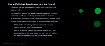
It's rare now to find an application that runs exclusively in one homogeneous environment. Users are now global, and enterprises must support applications that are always-on and available. These applications must also scale to meet demand while continuing to run efficiently, continuously delivering a positive user experience with minimal cost. Introduction In F5’s 2024 State of Application Strategy Report, Hybrid and Multicloud deployments are pervasive. With the need for flexibility and resilience, most businesses will deploy applications that span multiple clouds and use complex hybrid environments. In the following solution, we walk through how an organization can expand and scale an application that has matured and now needs to be highly-available to internal users while also being accessible to external partners and customers at scale. Enterprises using different form-factors such as F5 BIG-IP TMOS and F5 Distributed Cloud can quickly right-size and scale legacy and modern applications that were originally only available in an on-prem datacenter. Secure & Scale Applications Let’s consider the following example. Bookinfo is an enterprise application running in an on-prem datacenter that only internal employees use. This application provides product information and details that the business’ users access from an on-site call center in another building on the campus. To secure the application and make it highly-available, the enterprise has deployed an F5 BIG-IP TMOS in front of each of endpoint An endpoint is the combination of an IP, port, and service URL. In this scenario, our app has endpoints for the frontend product page and backend resources that only the product page pulls from. Internal on-prem users access the app with internal DNS on BIG-IP TMOS. GSLB on the device sends another class of internal users, who aren’t on campus and access by VPN, to the public cloud frontend in AWS. The frontend that runs in AWS can scale with demand, allowing it to expand as needed to serve an influx of external users. Both internal users who are off-campus and external users will now always connect to the frontend in AWS through the F5 Global Network and Regional Edges with Distributed Cloud DNS and App Connect. Enabling the frontend for the app in AWS, it now needs to pull data from backend services that still run on-prem. Expanding the frontend requires additional connectivity, and to do that we first deploy an F5 Distributed Cloud Customer Edge (CE) to the on-prem datacenter. The CE connects to the F5 Global Network and it extends Distributed Cloud Services, such as DNS and Service Discovery, WAF, API Security, DDoS, and Bot protection to apps running on BIG-IP. These protections not only secure the app but also help reduce unnecessary traffic to the on-prem datacenter. With Distributed Cloud connecting the public cloud and on-prem datacenter, Service Discovery is configured on the CE on-prem. This makes a catalog of apps (virtual servers) on the BIG-IP available to Distributed Cloud App Connect. Using App Connect with managed DNS, Distributed Cloud automatically creates the fully qualified domain name (FQDN) for external users to access the app publicly, and it uses Service Discovery to make the backend services running on the BIG-IP available to the frontend in AWS. Here are the virtual servers running on BIG-IP. Two of the virtual servers, “details” and “reviews,” need to be made available to the frontend in AWS while continuing to work for the frontend that’s on-prem. To make the virtual servers on BIG-IP available as upstream servers in App Connect, all that’s needed is to click “Add HTTP Load Balancer” directly from the Discovered Services menu. To make the details and reviews sevices that are on-prem available to the frontend product page in AWS, we advertise each of their virtual servers on BIG-IP to only the CE running in AWS. The menu below makes this possible with only a few clicks as service discovery eliminates the need to find the virtual IP and port for each virtual server. Because the CE in AWS runs within Kubernetes, the name of the new service being advertised is recognized by the frontend product page and is automatically handled by the CE. This creates a split-DNS situation where an internal client can resolve and access both the internal on-prem and external AWS versions of the app. The subdomain “external.f5-cloud-demo.com” is now resolved by Distributed Cloud DNS, and “on-prem.f5-cloud-demo.com” is resolved by the BIG-IP. When combined with GSLB, internal users who aren’t on campus and use a VPN will be redirected to the external version of the app. Demo The following video explains this solution in greater detail, showing how to configure connectivity to each service the app uses, as well as how the app looks to internal and external users. (Note: it looks and works identically! Just the way it should be and with minimal time needed to configure it). Key Takeaways BIG-IP TMOS has long delivered best-in-class service with high-availability and scale to enterprise and complex applications. When integrated with Distributed Cloud, freely expand and migrate application services regardless of the deployment model (on-prem, cloud, and edge). This combination leverages cloud environments for extreme scale and global availability while freeing up resources on-prem that would be needed to scrub and sanitize traffic. Conclusion Using the BIG-IP platform with Distributed Cloud services addresses key challenges that enterprises face today: whether it's making internal apps available globally to workforces in multiple regions or scaling services without purchasing more fixed-cost on-prem resources. F5 has the products to unlock your enterprise’s growth potential while keeping resources nimble. Check out the select resources below to explore more about the products and services featured in this solution. Additional Resources Solution Overview: Distributed Cloud DNS Solution Overview: One DNS – Four Expressions Interactive Demo: Distributed Cloud DNS at F5 DevCentral: The Power of &: F5 Hybrid DNS solution F5 Hybrid Security Architectures: One WAF Engine, Total Flexibility669Views1like0CommentsUsing BIG-IP GTM to Integrate with Amazon Web Services
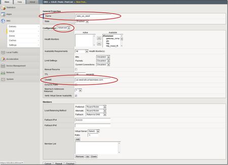
This is the latest in a series of DNS articles that I've been writing over the past couple of months. This article is taken from a fantastic solution that Joe Cassidy developed. So, thanks to Joe for developing this solution, and thanks for the opportunity to write about it here on DevCentral. As a quick reminder, my first six articles are: Let's Talk DNS on DevCentral DNS The F5 Way: A Paradigm Shift DNS Express and Zone Transfers The BIG-IP GTM: Configuring DNSSEC DNS on the BIG-IP: IPv6 to IPv4 Translation DNS Caching The Scenario Let's say you are an F5 customer who has external GTMs and LTMs in your environment, but you are not leveraging them for your main website (example.com). Your website is a zone sitting on your windows DNS servers in your DMZ that round robin load balance to some backend webservers. You've heard all about the benefits of the cloud (and rightfully so), and you want to move your web content to the Amazon Cloud. Nice choice! As you were making the move to Amazon, you were given instructions by Amazon to just CNAME your domain to two unique Amazon Elastic Load Balanced (ELB) domains. Amazon’s requests were not feasible for a few reasons...one of which is that it breaks the RFC. So, you engage in a series of architecture meetings to figure all this stuff out. Amazon told your Active Directory/DNS team to CNAME www.example.com and example.com to two AWS clusters: us-east.elb.amazonaws.com and us-west.elb.amazonaws.com. You couldn't use Microsoft DNS to perform a basic CNAME of these records because of the BIND limitation of CNAME'ing a single A record to multiple aliases. Additionally, you couldn't point to IPs because Amazon said they will be using dynamic IPs for your platform. So, what to do, right? The Solution The good news is that you can use the functionality and flexibility of your F5 technology to easily solve this problem. Here are a few steps that will guide you through this specific scenario: Redirect requests for http://example.com to http://www.example.com and apply it to your Virtual Server (1.2.3.4:80). You can redirect using HTTP Class profiles (v11.3 and prior) or using a policy with Centralized Policy Matching (v11.4 and newer) or you can always write an iRule to redirect! Make www.example.com a CNAME record to example.lb.example.com; where *.lb.example.com is a sub-delegated zone of example.com that resides on your BIG-IP GTM. Create a global traffic pool “aws_us_east” that contains no members but rather a CNAME to us-east.elb.amazonaws.com. Create another global traffic pool “aws_us_west” that contains no members but rather a CNAME to us-west.elb.amazonaws.com. The following screenshot shows the details of creating the global traffic pools (using v11.5). Notice you have to select the "Advanced" configuration to add the CNAME. Create a global traffic Wide IP example.lb.example.com with two pool members “aws_us_east” and “aws_us_west”. The following screenshot shows the details. Create two global traffic regions: “eastern” and “western”. The screenshot below shows the details of creating the traffic regions. Create global traffic topology records using "Request Source: Region is eastern" and "Destination Pool is aws_us_east". Repeat this for the western region using the aws_us_west pool. The screenshot below shows the details of creating these records. Modify Pool settings under Wide IP www.example.com to use "Topology" as load balancing method. See the screenshot below for details. How it all works... Here's the flow of events that take place as a user types in the web address and ultimately receives the correct IP address. External client types http://example.com into their web browser Internet DNS resolution takes place and maps example.com to your Virtual Server address: IN A 1.2.3.4 An HTTP request is directed to 1.2.3.4:80 Your LTM checks for a profile, the HTTP profile is enabled, the redirect request is applied, and redirect user request with 301 response code is executed External client receives 301 response code and their browser makes a new request to http://www.example.com Internet DNS resolution takes place and maps www.example.com to IN CNAME example.lb.example.com Internet DNS resolution continues mapping example.lb.example.com to your GTM configured Wide IP The Wide IP load balances the request to one of the pools based on the configured logic: Round Robin, Global Availability, Topology or Ratio (we chose "Topology" for our solution) The GTM-configured pool contains a CNAME to either us_east or us_west AWS data centers Internet DNS resolution takes place mapping the request to the ELB hostname (i.e. us-west.elb.amazonaws.com) and gives two A records External client http request is mapped to one of the returned IP addresses And, there you have it. With this solution, you can integrate AWS using your existing LTM and GTM technology! I hope this helps, and I hope you can implement this and other solutions using all the flexibility and power of your F5 technology.3.9KViews1like14Comments
Configuring BIG-IP for Zone Transfer and DNSSEC
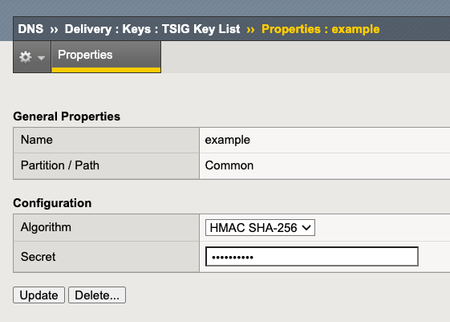
This article is for organizations that use our F5 BIG-IP as their primary DNS. The guide consists of two parts. First, it shows you how to configure BIG-IP DNS to perform a zone transfer to a secondary DNS server. Second, it demonstrates how to enable DNSSEC (Domain Name System Security Extensions) on BIG-IP DNS. Part 1: Configure BIG-IP DNS for Zone Transfer This part of the article will focus on guiding you on how to set up BIG-IP for zone transfer. I assume at this point in time that you already have DNS records configured via Zone Runner. Having said that, let's proceed to set up BIG-IP for zone transfer to a secondary DNS, which in our case will be F5 Distributed Cloud DNS. Step 1: Create a custom DNS Profile On the Main tab, click DNS > Delivery > Profiles. click Create. Type a Name for the custom DNS profile. Select 'dns' as the Parent Profile from which it will inherits settings. Under DNS Traffic area, Zone Transfer, select Enabled. Click Save & Close. Step 2: Create a custom DNS Listener On the Main tab, click DNS > Delivery > Listeners, click Create. In the Name field, type a unique name for the listener. For the Destination setting, in the Address field, type an IPv4 address on which BIG-IP DNS listens for network traffic. In the Service area, from the Protocol list, select UDP. In the Service area, from the DNS Profile list, select the custom profile created on Step 1. Click Finished. Repeat steps 1-6 to create a TCP listener, but on step 4, select TCP. Step 3: Generate a TSIG Key On BIG-IP DNS Command Line, enter the following in bash: tsig-keygen -a HMAC-SHA256 <tsig name> Example: tsig-keygen -a HMAC-SHA256 example The output should be similar to this key "example" { algorithm hmac-sha256; secret "UAHXLiErXSTXw84QcaeWk2jLnU0GYXGWBQ2IT+rtfCU="; }; Step 4: Configure TSIG Key In the BIG-IP GUI, go to DNS > Delivery > Keys > TSIG Key List, click Create. Name: example Algorithm: HMAC SHA-256 Secret: <paste the secret output generated from Step 3> Step 5: Create Nameservers Go to DNS > Delivery > Nameservers > Nameserver List, click Create. Create the following nameserver objects: Name: localbind, Address: 127.0.0.1, Service Port: 53 Name: f5xcdns1, Address: 52.14.213.208, Service Port: 53, TSIG Key: example Name: f5xcdns2, Address: 3.140.118.214, Service Port: 53, TSIG Key: example The IP address details of F5XC to be used in Zone Transfers can be found here https://docs.cloud.f5.com/docs/reference/network-cloud-ref Step 6: Create DNS Zone for Zone Transfer Go to DNS > Zones > Zones > Zones List, click Create. Fill the following details: Name: f5sg.com DNS Express :: Server: localbind Zone Transfer Clients :: Nameservers: Select f5xcdns1 & f5xcdns2 TSIG :: Server Key: example Step 7: Include TSIG in named.conf On BIG-IP command line, create and open a new file named tsig.key in the /var/named/config directory. For example, use vi editor to create a new file named tsig.key in the /var/named/config directory, enter the following command: vi /var/named/config/tsig.key To add the TSIG key, paste the following output we generated earlier: key "example" { algorithm hmac-sha256; secret "UAHXLiErXSTXw84QcaeWk2jLnU0GYXGWBQ2IT+rtfCU="; }; Save the tsig.key file. To create the necessary symbolic link to the tsig.key file in the /config directory, enter the following command: ln -s /var/named/config/tsig.key /config/tsig.key To set the correct owner for the tsig.key file, enter the following command: chown named:named /var/named/config/tsig.key Using a text editor, open the /var/named/config/named.conf file for editing. For example, to use vi editor to edit the /var/named/config/named.conf file, enter the following command: vi /var/named/config/named.conf Add the following include statement to the top of the named.conf file, below the first two comments in the file: include "/config/tsig.key"; Save the file. Step 8: Add the Secondary DNS (F5XC DNS) IP addresses in Zone Transfer allow list Using a text editor, open the /var/named/config/named.conf file for editing. For example, to use vi editor to edit the /var/named/config/named.conf file, enter the following command: vi /var/named/config/named.conf Add the following acl statement at the bottom of the named.conf file (Note: The IP address details of F5XC to be used in Zone Transfers can be found here https://docs.cloud.f5.com/docs/reference/network-cloud-ref) acl "F5XC" { 52.14.213.208/32; 3.140.118.214/32; }; Insert the following inside the allow-transfer block (this will allow F5XC to perform AXFR requests) allow-transfer { localhost; F5XC; <--- Add this line }; Save the file (Optional) Part 2: Configure a BIG-IP DNS Zone for DNSSEC Assuming you already have a zone configured for DNS zone transfer and you want to enable DNSSEC on this zone, you can follow the steps below. The generated cryptographic keys for DNSSEC will be synced to the secondary DNS as part of the zone transfer. Step 1: Create automatically-managed zone-signing keys (ZSK) On the Main tab, DNS > Delivery > Keys > DNSSEC Key List, click Create. In the Name field, type a name for the key (Zone names are limited to 63 characters) From the Type list, select Zone Signing Key. From the State list, select Enabled. **You can leave all other setting to default and click Finish on this point. But if you can also modify other settings based on your requirement Click Finished. Step 2: Create automatically-managed zone-signing keys (KSK) On the Main tab, DNS > Delivery > Keys > DNSSEC Key List, click Create. In the Name field, type a name for the key (Zone names are limited to 63 characters) From the Type list, select Key Signing Key. From the State list, select Enabled. **You can leave all other setting to default and click Finish on this point. But if you can also modify other settings based on your requirement Click Finished. Step 3: Creating a DNSSEC zone On the Main tab, click DNS > Zones > DNSSEC Zones, click Create. In the Name field, type a domain name. For example, use a zone name of f5sg.com to handle DNSSEC requests for www.f5sg.com and *.www.f5sg.com. From the State list, select Enabled. For the Zone Signing Key setting, assign at least one enabled zone-signing key to the zone. You can associate the same zone-signing key with multiple zones. For the Key Signing Key setting, assign at least one enabled key-signing key to the zone. You can associate the same key-signing key with multiple zones. Click Finished. Step 4: Upload generated DS record to parent zone Upload the DS records for this zone to the organization that manages the parent zone. The administrators of the parent zone sign the DS record with their own key and upload it to their zone. You can find the DS records in the Configuration utility.1.4KViews4likes0Comments