cloud
1776 TopicsSingle-click CDN Experience for F5 Distributed Cloud Load Balancers
Fundamentals The modern CDN has evolved well beyond cache and serve. Today’s platforms are intelligent edge fabrics that combine performance optimization, layered security, multicloud routing, and even workload execution at the edge. Few products embody this evolution more completely than F5 Distributed Cloud CDN, and this post explores both why CDNs matter and what sets F5’s newest approach apart. At its core, a CDN is a globally distributed system of edge servers, called PoPs or Regional Edges (RE), that cache content and handle user requests on behalf of the server origin. When a user requests a resource, DNS resolution routes them to the nearest PoP. If the resource is cached there (a “cache hit”), it’s returned immediately. If not (a “cache miss”), the PoP fetches it from the origin, stores it, and returns it to the user. The speed improvement isn’t just perceptual. Reduced Round-Trip Time (RTT) correlates directly with business outcomes. Every page load shaved makes a difference for search rankings, checkout completion, and ad viewability all improve with lower latency. CDNs don’t just make things faster; they make digital businesses more competitive. To put the difference in concrete terms, here’s how a typical 200KB page might deliver across different scenarios. Platform deep dive Traditional CDNs optimize for one thing: getting cached bytes to users fast. Distributed Cloud CDN starts there but doesn’t stop, it's engineered as a unified platform where content delivery, application security, multicloud connectivity, and edge compute converge under a single operational surface. F5’s approach is architecturally distinct Most CDNs are standalone services that organizations integrate with separate security tools, load balancers, and observability stacks. The operational overhead of stitching these together and keeping policies consistent across them is substantial. F5 takes a different approach: CDN is one capability within the broader Distributed Cloud Platform, meaning it inherits the platform’s DNS, load balancing, WAF, observability, and multicloud networking services. The practical result, noted by enterprise users, is that WAF rules, DDoS policies, and CDN configurations all live in the same console. There’s no context switching between vendors, no policy drift between your security tool and your delivery tool, and no blind spots at the handoff between them. In the newest product update, anyone already using a Distributed Cloud Load Balancer can enable CDN acceleration with a single click: no rearchitecting, no new deployments. Built-in cacheability insights estimate performance improvement and cost savings before activation, so teams can make informed decisions without guesswork. Target use cases: Where F5 Distributed Cloud CDN fits best There are three primary use-case families for enabling an integrated CDN: Secure apps everywhere (WAAP + CDN): Organizations that need comprehensive web app and API protection with WAF, DDoS, bot defense, unified content delivery under a single policy plane and management console. Modern digital experiences: Dynamic, personalized applications spanning multiple public clouds, edge locations, and on-premises infrastructure that need consistent delivery regardless of where origin workloads live. Multicloud & edge initiatives: Enterprises migrating workloads across cloud providers or deploying edge compute who need a platform that bridges delivery, security, and service mesh without re-platforming for each environment. Visibility & Control: You can’t optimize what you can’t see F5’s Distributed Cloud Platform ships with unified observability that spans delivery performance and security posture. Real-time dashboards expose traffic patterns, cache efficiency metrics, origin health, and security event timelines, all from the same interface used to configure policies. Cache efficiency isn’t a static attribute either. Distributed Cloud CDN provides granular control over cache keys, TTL values, and path or header-based caching rules, enabling teams to optimize hit rates for specific content types and access patterns. Cacheability insights indicate which web apps are candidates for acceleration. For security operations, the edge generates rich telemetry: request rates, blocked attack types, geographic traffic distribution, and bot classification outcomes. This feeds into the same observability layer as performance data, giving teams a single pane of glass rather than separate dashboards for CDN and security. The recently announced F5 Insight capability extends this further, bringing OpenTelemetry-powered observability across BIG-IP, NGINX, and Distributed Cloud Services, consolidating performance and security intelligence across an organization’s entire F5 footprint into actionable, unified visibility. Demo Walkthrough Final thoughts A CDN is no longer an optimization. It’s table stakes for any organization serving digital experiences to a geographically distributed audience. The question isn’t whether to deploy one, but which platform best aligns with the complexity of your architecture and the ambition of your security posture. For organizations operating at the intersection of multicloud delivery, API-driven applications, and enterprise security requirements, Distributed Cloud CDN represents a compelling architectural choice: a platform that treats performance and security not as separate concerns to be stitched together, but as integrated properties of the same edge fabric. The bytes will always need to get from somewhere to your users. F5 makes that journey faster, safer, and smarter. Additional Resources Product information: https://www.f5.com/products/distributed-cloud-services/cdn Technical documentation: https://docs.cloud.f5.com/docs-v2/content-delivery-network/how-to/cdn-mgmt/conf-cache-lb Feature announcement blog: https://www.f5.com/company/blog/f5-distributed-cloud-cdn-faster-apps-one-click-enablement-lower-costs 284Views1like0Comments
Forwarding Logs to SIEM Tools via HTTP Proxy for F5 Distributed Cloud Global Log Receiver
Purpose This guide provides a solution for forwarding logs to SIEM tools that support syslog but lack HTTP/HTTPS ingestion capabilities. It covers the deployment and tuning of an HTTP Proxy log receiver configured to work with F5 Distributed Cloud (XC) Global Log Receiver settings. Audience: This guide is intended for technical professionals, including SecOps teams and Solution Architects, who are responsible for integrating SIEM tools with F5 XC Global Log Receiver. Readers should have a solid understanding of HTTP communication (methods, request body, reverse proxy), syslog, and data center network architecture. Familiarity with F5 XC concepts such as namespaces, log types, events, and XC-GLR is also required. Introduction: Problem Statement: SIEM tools often support syslog ingestion but lack HTTP/HTTPS log reception capabilities. Objective: Explain how to deploy and configure an HTTP Proxy to forward logs to F5 Distributed Cloud Global Log Receiver. Solution Overview: Architecture Diagram and workflow: Configuration Steps: Configure Global Log Receiver in F5 Distributed Cloud Console Navigate to: Home → Shared Configuration → Global Log Receiver Create or edit the Global Log Receiver settings for HTTP receiver Ensure the Global Log Receiver batch size is based on the payload size expected from F5 NGINX. Example configuration snap: Set Up NGINX as an HTTPs Log Receiver Install NGINX on your designated server. Configure log_format Configure NGINX to accept HTTP POST requests only and forward access logs to syslog Example configuration snippet: log_format custom_log_format_1 escape=json $request_body; # Example: include request body only server { listen 443 ssl; server_name <logreceiver_server_name>; ssl_certificate /etc/ssl/<logreceiver_server_cert>; ssl_certificate_key /etc/ssl/<logreceiver_server_key>; # Other SSL/TLS configurations (e.g., protocols, ciphers) ssl_protocols TLSv1.2 TLSv1.3; ssl_ciphers HIGH:!aNULL:!MD5; client_body_in_single_buffer on; # The directive is recommended when using the $request_body variable, to save the number of copy operations involved client_body_in_file_only off; #default client_max_body_size 32M; # based on tuning gzip on; location /log_endpoint { # Allow only POST requests for sending log data limit_except POST { deny all; } # Configure access_log to write incoming data to a file # access_log /var/log/nginx/log_receiver.log custom_log_format_1; access_log syslog:server=127.0.0.1:514,facility=local7,tag=nginx,severity=info custom_log_format_1; proxy_pass http://localhost:8091/; # This dummy Internal server required to collect request_body variable. } } # dummy internal server to respond back 200 ok server { listen 8091; server_name localhost; location / { return 200 "Log received successfully."; } } Set Up rsyslog server Install/configure rsyslog on your designated server. Configure 60-nginx.conf file in /etc/rsyslog.d/ directory Sample 60-nginx.conf file #nginx.* @@127.0.0.1:514 :syslogtag, isequal, "[nginx]" /var/log/nginx-syslog/nginx-access-log.log OR Set Up BIG-IP as an HTTPs Log Receiver Syslog pool ltm pool glr_syslog_pool { members { <syslog-servr-ip>:514 { address <syslog-server-ip-address> session monitor-enabled state up } } monitor tcp } iRule for hsl logging when CLIENT_ACCEPTED priority 500 { set hsl_handle "" set request_body "" } when HTTP_REQUEST priority 500 { if { [HTTP::method] eq "POST" } { HTTP::collect [HTTP::header Content-Length] } else { HTTP::respond 200 content "data received" } } when HTTP_REQUEST_DATA priority 500 { set request_body [HTTP::payload] if { ! [info exists hsl_handle] || $hsl_handle eq "" } { set hsl_handle [HSL::open -proto UDP -pool "/Common/glr_syslog_pool"] } HSL::send $hsl_handle "<134> XC_LOG: $request_body" HTTP::respond 200 content "data received" HTTP::release } Virtual Server configuration ltm virtual vs-3 { destination <vs-ip>:443 ip-protocol tcp mask 255.255.255.255 profiles { demo-ent-merja-in { context clientside } http { } tcp { } } rules { <iRule-created-in-earlier-step> } serverssl-use-sni disabled source 0.0.0.0/0 source-address-translation { type automap } translate-address enabled translate-port enabled } rsyslog server config inputs #### The following modules are enabled in rsyslogd.conf module(load="omfile") module(load="imtcp") input(type="imtcp" port="514") ### /etc/rsyslog.d/70-bigip.conf template(name="F5_Format" type="string" string="%TIMESTAMP% %msg%\n") if ($msg contains "XC_LOG:") then { action( type="omfile" File="/var/log/10.1.20.177/f5_hsl_custom.log" Template="F5_Format" ) stop } References: F5 Distributed Cloud Global log receiver supports many log receivers natively: F5 Distributed Cloud Technical Knowledge page on "Configure Global Log receiver" Prerequisites: An external log collection system reachable publicly. The following IP address ranges are required to be added to your firewall's allowlist: 193.16.236.64/29 185.160.8.152/29635Views6likes0Comments
What's new in BIG-IP v21.1?
Introduction F5 has officially released BIG-IP v21.1, delivering cutting-edge innovations designed to meet the dynamic needs of businesses and organizations. This version introduces advanced features such as quantum-resistant cryptography, AI-driven enhancements, protocol protection, and significant strides in software modernization. Packed with fixes and powerful new capabilities, BIG-IP v21.1 strengthens the F5 Application Delivery and Security Platform (ADSP) by improving delivery, security, and deployment, ensuring your applications remain fast, secure, and simple to manage. PQC Readiness Support for Additional NIST-Compliant PQC Key Exchanges Building upon the groundwork laid in v17.5.0, BIG-IP v21.1 introduces expanded Post Quantum Cryptography (PQC) support. This release adds SecP + ML-KEM key exchanges, combining traditional cryptographic methods with quantum-resistant algorithms for hybrid cryptography. New Supported Key Exchanges: SecP256r1ML-KEM-768 SecP384r1ML-KEM-1024 These enhancements benefit organizations in government and regulated industries adhering to NIST guidelines and FIPS standards. Both client- and server-side connections are supported alongside SSL Forward Proxy use cases. Quantum-Resistant TLS/SSL VPN Tunneling As quantum computing emerges, traditional encryption methods face threats from advanced computational power. To counteract this, BIG-IP Zero Trust Access (formerly BIG-IP APM) introduces quantum-resistant TLS/SSL VPN tunneling with X25519 + ML-KEM-768 hybrid key exchanges. This solution ensures NIST compliance while securing modern VPN tunnels. AI Workload Delivery, Security, and Access Enhancements Expanded Security and Delivery for Model Context Protocol (MCP) BIG-IP v21.1 enhances MCP support to ensure secure and consistent communication between AI models, applications, and data sources. MCP Protection: BIG-IP Advanced WAF now inspects MCP traffic, shielding AI workflows from emerging threats such as tool poisoning, secret exposure, and injection attacks detailed in the OWASP MCP Top 10. A new Security Policy template called MCP Protection Policy has been added: A new Blocking Page Response type has been added. The MCP Session ID is included in the Response Headers: The MCP Request ID is included in the Response Body: Sample response for an “Echo tool”: Sample rejected response: MCP Session Persistence: New session persistence for MCP traffic ensures smoother workflows by consistently routing session requests to the correct server. A new MCP Persistence Profile aimcp has been added: Optimized Agent-to-Agent Connectivity The introduction of experimental support for the Agent2Agent (A2A) protocol optimizes communication between AI agents, ensuring interoperability across fragmented platforms. Features Include: Load balancing for A2A traffic. Governance via iRules based logging and visibility. While experimental in v21.1, future releases promise full support with expanded management capabilities. Seamless, Secure Access for AI Agents The Dynamic Client Registration (DCR) capability expedites access requests for agentic AI systems. Agents can register themselves programmatically with BIG-IP Zero Trust Access, eliminating manual steps and streamlining workflows via API driven automation. F5 BIG-IP Zero Trust Access enables dynamic client registration to expedite access requests. Modern API and Protocol Protection HTTP/3 Protocol Traffic Security With HTTP/3 adoption expected to surpass HTTP/2 soon, BIG-IP Advanced WAF brings cutting edge protection for HTTP/3 traffic, matching the security levels of earlier protocol versions. Currently limited to client side protection, server side capabilities will follow in subsequent releases. OpenAPI 3.1 Specification Support BIG-IP Advanced WAF now protects APIs defined by OpenAPI 3.1, learning expected endpoints, data types, and security requirements while blocking improper requests, undocumented endpoint abuse, and API specific attacks. Previous OpenAPI versions (2.0, 3.0) remain supported. BIG-IP TMOS Software Modernization DNS Enhancements Multiple Response Policy Zones Feed Zones DNS security and efficiency are strengthened with the ability to configure and consolidate multiple RPZ feeds into a single DNS cache profile. Enhanced DNS Threat Mitigation Improved granularity allows IP-based blocking for malicious domains and dynamic responses to regional compliance mandates. Flexible DNS Response Actions Organizations gain flexibility to block, redirect, or manage traffic dynamically, streamlining DNS-level policy management. BIG-IP TMOS Software Modernization Introducing the New BIG-IP Declarative API Designed for modern application environments, the new BIG-IP Declarative API (in Alpha state) offers: Integrated lifecycle management. Per-app scalability for simplified configurations. Broadened automation capabilities with near real-time deployment. This marks a significant upgrade over AS3, empowering faster and more efficient automation workflows. Continued Control Plane Enhancements Control plane improvements focus on reliability, performance, and resource efficiency through upgrades to MCPd, iControl REST, and the BigD daemon. These enhancements: Speed up iControl REST API requests by up to 10%. Boost control-plane resilience under low-memory conditions. Enable multi-threaded scalability for BigD health monitoring. Expect recurring advancements across future BIG-IP versions. New Features in SSL Orchestrator v14 Policy-based Dynamic Egress Routing Policy-based dynamic egress routing is introduced in SSL Orchestrator that enables you to easily define egress routes based on traffic conditions, directly within the policy definition, thereby avoiding the need to configure complex layers involving multiple topologies and iRules. This feature is supported for Outbound and Inbound Gateway topologies. You can create a policy in BIG-IP LTM tailored to your routing requirements and then attach the policy to the SSL Orchestrator Virtual Server. This will ensure that the traffic is dynamically routed to the appropriate egress route based on the configurations defined within the LTM policy. L2 Devices Scalability Previously, SSL Orchestrator supported up to 8 physical devices per L2 Inspection Service. Now, SSL Orchestrator supports up to 50 devices per L2 Inspection Service, enabling greater scalability and flexibility. Inspection Service Persistence SSL Orchestrator now supports inspection service persistence, which enables client connections to consistently flow through the same inspection service, allowing it to track the entire user application flow seamlessly. This feature is supported for L2, L3, HTTP, and Advanced WAF off-box inspection services. A new Default Persistence Profile dropdown has been added to the Services page: Destination Address Affinity Hash Host (specific to HTTP services) Source Address Affinity SSL (for TCP Virtual Servers of L2/L3 services) Universal New Forcepoint URLDB Categories The following new Forcepoint URLDB categories have been added: Cryptocurrency (235): sites that provide digital currencies, decentralized financial services. Includes platforms facilitating cryptocurrency trading, wallets, ICOs, and blockchain-based financial services. Crypto Mining (236): sites that promote mining pools or enable crypto mining, including software downloads and browser-based mining scripts. Relaxed Protocol Compliance Rules for External Sites SSL Orchestrator now supports Relaxed HTTP Protocol Compliance by allowing you to select Transparent HTTP profiles to ease enforcement for non-compliant websites. This approach eliminates protocol disruptions and provides flexibility for forward proxy scenarios. The L7 Profile dropdown is introduced in Outbound Topology settings in the Interception Rules screen, which enables you to select a reverse or transparent HTTP Profile. By default, the topology specific http profile is used. HTTP Service: The Proxy Type dropdown is introduced. When you select Proxy Type as Transparent, the HTTP Profile dropdown will appear, allowing you to select the required HTTP transparent Profile. New Features in Zero Trust Access IPsec VPN Support Added support for Access IPsec VPN Tunnels, to meet global security standards and enable the transition from SSL/TLS-VPNs to IPsec VPNs. Clients can now connect to BIG-IP using the Windows Edge Client or F5 Access for macOS, establish an IPsec tunnel, and securely access the backend network. A new field, VPN Type, is introduced in the Connectivity Profile screen. When you set it to IPsec, the system automatically generates an Access IPsec Policy. HTTP Connector Support Added to Per-Session Policies in APM Support for the HTTP Connector in per-session policies is now available in F5 BIG-IP Access Policy Manager (APM). This feature enables administrators to send HTTP requests to external services during session establishment and use the response for authentication, authorization, and access control decisions. Dynamic Client Registration (DCR) support This release adds support for OAuth 2.0 Dynamic Client Registration (RFC 7591). Administrators can enable DCR on OAuth profiles to allow authorized clients to dynamically register using an Initial Access Token (IAT). The feature includes support for the Client Credentials grant type, configurable client authentication settings, client secret expiration, and enhanced logging. Custom Logging Preferences for Windows Edge Client The Windows Edge Client now offers custom logging preferences, giving you enhanced control over log verbosity to improve both security and flexibility. You can select the required log level from the APM Client Log Level drop-down in General Settings while creating a connectivity profile. Native Support for SAML Authentication for Windows APM clients now support native SAML authentication, significantly improving user experience, maintainability, and overall supportability. Edge Client on macOS and Windows can leverage the system’s default browser to authenticate users with identity providers (IdPs), enabling modern authentication mechanisms such as FIDO2 and Microsoft Entra ID device authentication. To enable this feature, select the Enable System Browser checkbox in Desktop Client Settings while creating a Connectivity Profile from Access > Connectivity / VPN > Connectivity > Profiles in BIG-IP. Auto-Upgrade Machine Tunnel Service Windows Edge Clients can now automatically upgrade the F5 Machine Tunnel Service when a newer version is available on BIG-IP, and the auto-upgrade feature is enabled. Additionally, if the Machine Tunnel service is running before the upgrade, it continues to run after the upgrade completes without affecting existing VPN configuration settings. Endpoint Inspection Support on Ubuntu with ARM64 Endpoint Inspection is now supported on Ubuntu with ARM64, allowing seamless management and inspection of endpoints on Linux ARM64 platforms. Conclusion Upgrade to BIG-IP v21.1 to unlock a new wave of features that enhance application delivery, security, and management. From PQC readiness and dynamic AI solutions to cutting-edge protocol protection, this release propels BIG-IP capabilities forward. Related Content BIG-IP v21.1 Release Notes Live Webinar on BIG-IP v21.1 Features Blog F5 BIG-IP v21.1 is now generally available, bringing PQC and AI security enhancements Feel free to reach out for additional resources or clarification. Happy upgrading!140Views1like0CommentsAutomating F5 ADSP — Part 1: F5 XC and BIG-IP for Delivery and Security
What this use case demonstrates This use case covers three of the four ADSP areas: Delivery, Security, and Deployment. Delivery — F5 Distributed Cloud (XC) load balancer at the edge, F5 BIG-IP LTM handling traffic management inside the VPC. Security — XC WAF at the edge, BIG-IP Advanced WAF (AWAF) applying in-path policy before traffic reaches the application servers. Deployment — XC consumed as SaaS, BIG-IP deployed as a Virtual Edition in GCP. Same article, two deployment models, both provisioned from code. You get two layers of delivery and two layers of WAF, across a SaaS edge and a self-managed VE. The whole stack, VPC through XC load balancer, comes up from a single git push. Architecture What gets deployed: A GCP VPC with management, external, internal, and application subnets BIG-IP with AWAF in a single-NIC configuration OWASP Juice Shop and crAPI as target applications F5 Distributed Cloud HTTP load balancer, origin pool, and WAF policy pointing at the BIG-IP The vulnerabilities in the apps are deliberate. They let you exercise the WAF stack against real attack signatures and API abuse patterns. Without them, you only know the controls deployed, not that they work. DevSecOps in practice The lead-in covers the approach. For UC1, that means: Terraform handles infrastructure, BIG-IP configuration, and F5 Distributed Cloud objects. No click-ops. State lives in a GCS bucket the workflow creates on the first run, with a separate state file per module. The same bucket carries the AS3 declaration BIG-IP pulls on boot, so the runner never needs network access to BIG-IP. GitHub Actions runs the pipeline. Branch names trigger deployments, so git history shows what was meant to happen. GCP Workload Identity Federation replaces static service account keys. The F5 XC API certificate lives in GitHub Actions secrets, not the repo. The pipeline Pushing to a branch runs the workflow. There is no manual terraform to apply. Action Branch Validate, plan, and apply deploy-adsp-uc1 Validate only (no apply) test-adsp-uc1 Destroy all resources destroy-adsp-uc1 This keeps intent visible in git, makes destroy as easy as deploying, and gives reviewers a real PR to look at when something changes. What's in the repo f5devcentral/F5-ADSP-Automation: Directory Purpose infra/gcp/ VPC, subnets, firewall rules compute/gcp/ Juice Shop and crAPI f5/ BIG-IP base config and AWAF policy config/uc1/gcp/env.json GCP project, region, prefix config/uc1/xc/env.json F5 Distributed Cloud config .github/workflows/ CI/CD workflows Demo Try it Prerequisites, secrets, and troubleshooting are in the Use Case Deployment Guide. Contribute Issues and PRs welcome at f5devcentral/F5-ADSP-Automation/Issues. Resources: F5 Application Delivery and Security Platform GitHub Repo and Automation Guide ADSP Architecture Article Series: Automating F5 ADSP Deployments (Intro) Automating F5 ADSP Deployments (Part 1 - F5 XC WAF and BIG-IP Adv. WAF) Automating F5 ADSP Deployments (Part 2 - F5 XC WAF and NGINX App Protect) Automating F5 ADSP Deployments (Part 3 - F5 XC API Protection and NGINX Ingress) Automating F5 ADSP Deployments (Part 4 - F5 XC BOT Defense and BIG-IP AdvWAF) Automating F5 ADSP Deployments (Part 5 - F5 XC, BIG-IP APM, CIS, and NGINX Ingress) Minimizing Security Complexity: Managing Distributed WAF Policies 110Views1like0Comments
Deploying an NGINX App across Kubernetes Multi-clusters with F5 BIG-IP Container Ingress Services
This tutorial simulates orchestrating multiple clusters using a single Kubernetes control plane with separate kubeconfig contexts, the same F5 CIS configuration patterns apply to genuinely separate Kubernetes clusters across different networks, cloud regions, or data centers. The simulation approach allows configuration testing without requiring multiple physical or cloud infrastructure environments.231Views1like0CommentsCustomer Edge as a Fallback for F5 Distributed Cloud Regional Edge
Introduction F5 Distributed Cloud Regional Edges (REs) form the backbone of F5’s globally distributed application delivery network. These F5-managed Points of Presence handle load balancing, Web Application Firewall (WAF) enforcement, bot protection, and API security for thousands of organizations worldwide. While F5 Regional Edges are engineered for extreme resilience—with built-in redundancy, geographic distribution, and continuous monitoring—no infrastructure is entirely immune to disruption. A defense-in-depth strategy demands that organizations consider even low-probability scenarios. This article explores how F5 Distributed Cloud Customer Edge (CE) nodes can serve as a fallback data path in the unlikely event of a Regional Edge outage, leveraging a capability that many organizations already have deployed but may not have considered for this purpose. Understanding the RE and CE Data Paths Regional Edge: The Default Path In a typical F5 Distributed Cloud deployment, application traffic follows this path: Client resolves the application’s FQDN via DNS DNS returns an F5 Regional Edge Anycast IP address Internet BGP routing directs the client to the nearest RE advertising that IP The RE terminates the connection, applies load balancing and security policies The RE forwards traffic to origin servers (directly or via CE nodes) The key mechanism here is IP Anycast. F5 Regional Edges advertise the same unicast IP address from multiple Points of Presence worldwide via BGP. When a client sends traffic to that IP, the internet’s BGP routing infrastructure naturally selects the shortest AS path—effectively directing the client to the geographically closest (or topologically nearest) RE. This means the DNS itself does not perform geographic selection. Every client worldwide receives the same IP address in the DNS response. It is the underlying BGP routing on the internet that ensures each client reaches its nearest RE. This is a fundamental difference from GeoDNS-based approaches, where different IPs are returned depending on the client’s location. Anycast routing typically delivers lower and more consistent latency than GeoDNS for several reasons: BGP routes on network topology, not geographic approximation. BGP is a path-vector protocol that selects routes based on AS path length, local preference, and policy attributes—not latency or congestion. However, in practice, routing to the topologically nearest PoP (fewest AS hops) generally correlates with reasonable latency, even if it is not optimized for it. GeoIP databases are approximations. GeoDNS relies on commercial GeoIP databases to map IP addresses to locations. These databases can be inaccurate or outdated. BGP doesn’t care about IP-to-location mapping; it routes based on actual network reachability. BGP adapts in real-time. If a link fails or a PoP goes offline, the BGP reconverges and traffic shifts to the next-best path automatically—often within seconds. GeoDNS is static until the DNS TTL expires. During that window, clients may continue hitting a degraded or unreachable endpoint. Regional Edges operate as a fully managed SaaS infrastructure. Organizations benefit from F5’s global Anycast network without deploying or maintaining edge nodes themselves. Customer Edge: The On-Premises Path Customer Edge nodes, typically deployed in on-premises data centers or customer cloud environments, can provide the same load balancing and WAF capabilities as Regional Edges. This is a critical but often underappreciated architectural property of the F5 Distributed Cloud platform. When a load balancer is configured in the F5 Distributed Cloud Console, it can be advertised on: Regional Edges only — the default for internet-facing applications Customer Edges only — common for internal applications Both Regional Edges and Customer Edges — the key to the fallback strategy described in this article The Shared Configuration Principle A single load balancer object in the F5 Distributed Cloud Console—with its full configuration including WAF policies, routes, rate limiting, and origin pools—can be advertised simultaneously on REs and CEs. There is no need to duplicate or maintain separate configurations. Aspect Regional Edge Customer Edge Load Balancing ✓ Same configuration ✓ Same configuration WAF / App Firewall ✓ Same policies ✓ Same policies Routes and Rewrites ✓ Same rules ✓ Same rules Origin Pool Selection ✓ Same pools ✓ Same pools Bot Defense ✓ ✓ API Protection ✓ ✓ Managed by F5 Customer Key Insight: This configuration parity is the foundation of the fallback strategy. The same security posture is enforced regardless of whether traffic enters through a RE or a CE. The Fallback Strategy: DNS-Based Traffic Switching How It Works The failover mechanism from Regional Edges to Customer Edges relies on a straightforward DNS change. Under normal operation, the application's DNS record points to the RE-assigned IP addresses. In a fallback scenario, the DNS record is updated to point to the public IP addresses of the Customer Edge nodes. Normal Operation: app.example.com → RE Anycast IP (e.g., 5.x.x.x, same IP globally) → BGP routing directs client to nearest Regional Edge → RE applies LB + WAF policies → RE forwards to origin Fallback Operation: app.example.com → CE Public IP (e.g., 203.0.113.10, standard unicast) → Client connects directly to Customer Edge (no Anycast routing) → CE applies the SAME LB + WAF policies → CE forwards to origin The application experience remains identical from the client's perspective in terms of security and functionality. The same policies are enforced, the same load balancing decisions are made, and the same origins are reached. The trade-off is that clients lose the Anycast proximity benefit—all traffic converges on the CE location(s) rather than being distributed to the nearest PoP. Prerequisites Before this strategy can be activated, several elements must be in place: The load balancer must be advertised on both REs and CEs. This is configured in the F5 Distributed Cloud Console under the load balancer's VIP advertisement settings. The CE advertisement must be active before an incident—configuring it during an outage adds delay and risk. The “Virtual Network“ type with value “ves-io-shared/public” is the equivalent of “Internet“ VIP advertisement. CE nodes must have public IP reachability. The CE's outside interface (or an NAT/firewall in front of it) must be reachable from the internet on the required ports (typically 443 and/or 80). This may require firewall rules, NAT configurations, or public IP assignments that should be validated in advance. CE nodes must have sufficient capacity for degraded-mode operation. Under normal operation, REs handle the full internet-facing traffic load. CEs used as fallback must be sized to sustain this traffic temporarily—long enough to bridge a RE outage, not to replace RE infrastructure indefinitely. This includes compute resources (CPU, memory), network bandwidth at the CE site, and upstream internet connectivity. DNS records must be prepared. The target CE IP addresses should be documented and ideally pre-staged in DNS management tooling so that the switchover can be executed rapidly. Important: All prerequisites must be validated before an incident occurs. A fallback strategy that hasn’t been tested is not a fallback strategy. Customer Edge: The On-Premises Path Customer Edge nodes, typically deployed in on-premises data centers or customer cloud environments, can provide the same load balancing and WAF capabilities as Regional Edges. This is a critical but often underappreciated architectural property of the F5 Distributed Cloud platform. When a load balancer is configured in the F5 Distributed Cloud Console, it can be advertised on: Regional Edges only — the default for internet-facing applications Customer Edges only — common for internal applications Both Regional Edges and Customer Edges — the key to the fallback strategy described in this article The Shared Configuration Principle A single load balancer object in the F5 Distributed Cloud Console—with its full configuration including WAF policies, routes, rate limiting, and origin pools—can be advertised simultaneously on REs and CEs. There is no need to duplicate or maintain separate configurations. Aspect Regional Edge Customer Edge Load Balancing ✓ Same configuration ✓ Same configuration WAF / App Firewall ✓ Same policies ✓ Same policies Routes and Rewrites ✓ Same rules ✓ Same rules Origin Pool Selection ✓ Same pools ✓ Same pools Bot Defense ✓ ✓ API Protection ✓ ✓ Managed by F5 Customer Key Insight: This configuration parity is the foundation of the fallback strategy. The same security posture is enforced regardless of whether traffic enters through a RE or a CE. DNS TTL: The Critical Factor Why TTL Matters The speed of a DNS-based failover is fundamentally governed by the Time-To-Live (TTL) value set on the application’s DNS records. TTL determines how long DNS resolvers and clients cache a DNS response before querying again. TTL Value Effective Switchover Time Trade-off 3600 (1 hour) Up to 1 hour Minimal DNS query load, slow failover 300 (5 minutes) Up to 5 minutes Moderate query load, reasonable failover 60 (1 minute) Up to 1 minute Higher query load, fast failover 30 (30 seconds) Up to 30 seconds Significant query load, near-instant failover Critical: TTL must be set before an incident occurs. Lowering TTL during an outage has no effect on records already cached by resolvers worldwide. The old, higher TTL continues to govern those cached entries until they expire naturally. Recommended Approach For organizations that consider CE fullbacks as part of their resilience strategy: Proactive TTL reduction: Set DNS TTL to 60–300 seconds on records that may need failover. This should be steady-state TTL, not an emergency change. Pre-incident preparation: Ensure the DNS change procedure is documented, tested, and can be executed by on-call staff within minutes. Automated failover (advanced): Integrate health checks on RE endpoints with DNS automation (via API calls to your DNS provider) to trigger the switch automatically. The TTL Reality Check Even with low TTL values, some clients and intermediate resolvers do not strictly honor TTL: Stub resolvers on end-user devices may cache beyond the stated TTL Some enterprise DNS resolvers impose minimum TTL floors (commonly 30–60 seconds) Browser DNS caches may hold entries independently of the OS resolver Connection keep-alive means existing TCP/TLS sessions continue to the old IP even after DNS changes Organizations should expect a gradual migration of traffic rather than an instantaneous cutover, even with aggressive TTL values. Plan for a transition window of several minutes during which traffic flows to both the old and new endpoints. Operational Caveats and Considerations Capacity Planning Under normal operations, Regional Edges absorb the full internet-facing traffic load across F5’s globally distributed infrastructure. Switching to Customer Edges concentrates this traffic onto a much smaller set of nodes, typically in one or two locations. Factor Regional Edges Customer Edges (Fallback) Geographic distribution Global Limited (customer sites) Bandwidth F5 backbone Customer uplink DDoS absorption F5 scrubbing capacity Customer/ISP capacity Horizontal scale Elastic Fixed (pre-provisioned) Recommendation: Conduct periodic load testing against CE nodes to validate they can sustain the expected RE traffic volume for a limited duration. CE infrastructure does not need to match RE capacity long-term, but it must hold up long enough to bridge an outage window without service degradation. DDoS Protection F5 Regional Edges benefit from F5’s network-level DDoS mitigation infrastructure. When traffic is redirected to Customer Edge nodes, this protection layer is bypassed. The CE site’s internet uplink becomes the direct target for any volumetric attack. Mitigation options: Ensure the CE site has upstream DDoS protection from the ISP or a dedicated scrubbing service Consider maintaining a DDoS-protected IP transit for CE public addresses If using BGP-routed DDoS protection, ensure CE public prefixes are covered Failover Workflow When a RE outage is confirmed and the decision to fail over is made, the procedure is: Step 1: Update DNS Records Change the application’s DNS A record (or AAAA for IPv6) from the RE IP addresses to the CE public IP addresses. If multiple CEs are available, configure multiple A records or use the BGP/ECMP architecture described in Part One of this series to distribute traffic across CEs behind a single public IP. Step 2: Monitor the Transition Observe traffic shifting to CEs as DNS caches expire. Expect a gradual ramp-up over a period aligned with your DNS TTL. Monitor CE resource utilization, error rates, and application response times. Step 3: Restore Normal Operation Once RE services are restored, reverse the DNS change to point back to RE IP addresses. Again, the transition back follows the same TTL-governed timeline. Validate that traffic has fully returned to the RE path before considering any CE-specific fallback infrastructure changes. Conclusion F5 Distributed Cloud Customer Edges provide a credible fallback path for the unlikely scenario of a Regional Edge outage. The platform’s ability to advertise a single load balancer—with identical configuration, WAF policies, and origin pools—on both REs and CEs is the enabling feature that makes this strategy viable without configuration duplication or drift. The key success factors are preparation and proactive configuration: DNS TTL must be set low before an incident, not during one CE capacity must be sufficient to handle traffic load in a degraded mode—this is a temporary measure, not a long-term replacement for RE infrastructure The full failover procedure must be tested periodically to remain viable Operational caveats—latency, DDoS exposure, session interruption—must be understood and accepted as part of the failover trade-off This approach does not replace the resilience built into F5’s Regional Edge infrastructure. Rather, it provides an additional layer of organizational confidence: even in a worst-case scenario, the application delivery path can be restored using infrastructure the organization already controls.197Views2likes0CommentsHow to use F5 Distributed Cloud to block (OFAC) Sanctioned Countries
Over the last several days, the climate has changed significantly in Eastern Europe, and I have been getting asked a lot about the possibility of blocking Office of Foreign Assets Control - Sanctioned Countries (OFAC) with F5 Distributed Cloud, and how to do it. The answer is quite simple; yes we can do it and its a pretty simple configuration. I think its also important to point out that this same process can be used to configure any other required GeoFencing policies as well. Do we also have ways to block DDOS and provide WAAP services? Also yes, but outside the scope of this article. In this article, I will focus on how to deploy & create: [Namespace] Service Policies Origin Pool(s) to send traffic to Distributed listener / load balancer with the security policy assigned View Security Events. Level Set Most of this article will be based around ClickOps deployment of this use-case. That said, the F5 Distributed Cloud is an API first platform, so everything can be done with your tools of choice for interaction with declarative APIs. I will include JSON manifests of the configured items as well to provide examples of what delcarations will resemble, as well as support direct import into the distributed cloud. It would be possible to say, set the policy configuration JSON into github as a source of truth, and have webhooks set up to push to the platform any time a change is made to ensure configurations stay within proper alignment. Who do we block? Before we can start blocking things, we need to know what exactly to block, so we need to acquire a list of OFAC Sanctioned Countries. There are a couple of options here as well. CSV straight from the source: https://home.treasury.gov/policy-issues/office-of-foreign-assets-control-sanctions-programs-and-information Dig through available data sources on Data.Gov: https://catalog.data.gov/dataset/consolidated-non-sdn-sanctions-list Third Party ACL Sites like Country Block List: https://www.countryipblocks.net/ofac.php (I cannot personally vouch for the accuracy of this content.) For the sake of brevity here, I will focus on just some top level country sanctions based on country code versus IP Subnet, but thats up to preference. Configuration Log in to your F5 Distributed Cloud Console. (If you do not have a tenant today, you should reach out to your F5 Account Team immediately and rectify the situation!) Service Policies for everyone! There are a couple of options for service policies in the platform. Shared Policies: Policies created in the Shared namespace, can be shared globally within your tenant. Benefit: Globally set policy baseline for all applications in your tenant. Namespace Policies: Policies created in a Namespace can only be shared within that namespace. Benefit: Namespace service policies applied by default to all listeners / load balancers. For this example, we will create the policy in a namespace. From the tiles, select Load Balancers, and then we need to ensure that we are in the proper namespace. (As with everyting on the platform, there are multiple ways to get places, and multple ways to configure things, so this will only cover 1 example of how.) Now we need to expand Security, hover over Service Policies, Click Service Policies, and in the new window click Add service policy. Populate the Name under metadata, leave attachment as Any Server, and set Select Policy Rules to Denied Sources. Now, we could use IP blocks, but for this example we will just use the Country List configuration parameter and enter country codes. This will pull from GeoIP validation. UPDATE: I have been getting a lot of notes on this article based on Ukraine versus Crimea, and how to specify since its not seperated out as a country code. Can we Allow Ukraine and block Crimea? Absolutely! For Crimea, we need to pull from another database, so for this example I am going to pull from https://bgpview.io/search/Crimea and we are going to block by ASN. So within our service policy, click Add item under BGP ASN Set. And on this screen we enter in all the ASN's that we discovered from the previous link. Then click Apply. (Making sure to now remove Ukraine from our Block List.) Then we need to determine Default Action. This is where you can cause some pain for yourself, so pay special attention when selecting Default action (“Default Action for requests from sources that do not belong to this list”), if you are using Next Policy, ensure the next policy allows traffic, or set the Default action to Allow, or the application will not receive any traffic. In this example I will only be using one policy, so I will set the Default Action to Allow (as noted in the JSON). Save and Exit. UPDATE 2: OK, you guys are killing me! Can we go to City Level or target regions outside of ASN? Yes! Here is how you do that. (I should plan better in the future for less edits!) Just to keep things clean, lets add a new Service Policy. This time, under Select Policy Rules, we are going to select Custom Rule List from the drop down. Then from here, we want to click Configure under Rules, then Add Item. Give our new rule a name, and click Configure under Rule Specification. From here, we are going to change the dropdown under Clients - Client Selection from Any Client to Group of Clients by Label Selector. Then under Selector Expression, Add Label. In the available selections you will find geoip.ves.io/city, country, and region (as well as some really cool IP Intelligence options but those are out of scope for this article.). Lets do a Region first to see how that works. Selct geoip.ves.io/region, then =, then start typing a region, for example Crimea. Once we have it set, scroll down and click Apply. Now, lets add another rule, but this time we are going to select city. We are already blocking Russia in our earlier policy, but just for an example lets add = Moscow. Now scroll down and click Apply. Thats it! Now we have policies to block based on GeoIP Country, Region, and City, as well as BGP ASN. We can apply all of them to our application at the same time. Now, lets say you just want to cheat, and copy and paste some JSON in, or you want to build it into a pipeline. You can go and check out the API specifications for Service Policy here: https://docs.cloud.f5.com/docs/api/service-policy The JSON would resemble the following for our first policy: { "metadata": { "name": "coleman-ofac-deny", "namespace": "m-coleman", "labels": {}, "annotations": {}, "description": "", "disable": false }, "spec": { "algo": "FIRST_MATCH", "any_server": {}, "rules": [ { "kind": "service_policy_rule", "uid": "c12f8c5d-44c2-495c-83e8-30842e9e0a7f", "tenant": "f5-sa-rnxeudss", "namespace": "m-coleman", "name": "ves-io-service-policy-coleman-ofac-deny-asn-list" }, { "kind": "service_policy_rule", "uid": "5d24d0d0-6c6b-4c7b-b5b3-4bec67c2ffed", "tenant": "f5-sa-rnxeudss", "namespace": "m-coleman", "name": "ves-io-service-policy-coleman-ofac-deny-country-list" }, { "kind": "service_policy_rule", "uid": "f9df0b83-21de-4c13-aebf-4e27fc580ed0", "tenant": "f5-sa-rnxeudss", "namespace": "m-coleman", "name": "ves-io-service-policy-coleman-ofac-deny-default-action" } ], "deny_list": { "ip_prefix_set": [], "asn_list": { "as_numbers": [ 204791, 205515, 208090, 28761, 41269, 43222, 43564, 49617, 59744, 8654 ] }, "asn_set": [], "country_list": [ "COUNTRY_BY", "COUNTRY_BA", "COUNTRY_BI", "COUNTRY_CF", "COUNTRY_CU", "COUNTRY_IR", "COUNTRY_IQ", "COUNTRY_KP", "COUNTRY_XK", "COUNTRY_LY", "COUNTRY_MK", "COUNTRY_SO", "COUNTRY_SD", "COUNTRY_SY", "COUNTRY_ZW", "COUNTRY_CD", "COUNTRY_LB", "COUNTRY_NI", "COUNTRY_RU", "COUNTRY_SS", "COUNTRY_VE", "COUNTRY_YE" ], "tls_fingerprint_classes": [], "tls_fingerprint_values": [], "default_action_allow": {} }, "simple_rules": [] } } And our second policy JSON puts us over the limit for the article, but all JSON from these configs are in the attached file. Origin Pools Origin Pools are where we send traffic to, so if you are familiar with BIG-IP its just the Pool, and if you are familiar with NGINX its our Upstream. All of the settings and nerd knobs that are part of origin pools are out of scope of this article, so we are just going to point our origin at a single public IP and move on. To create an Origin Pool, Expand the Manage Block, hover over Load Balancers, click Origin Pools, and then Add Origin Pool. Give the Origin Pool a Name under Metadata. Then under Origin Servers click Add Item so we can add an upstream server. For this example I am going to use a Public DNS Name of Origin Server, but you should use whichever applies best to your situation. Click Add Item once done, which will return us to the Origin Pool Config. Make sure to select the correct port, and any TLS settings for your environment. Click Save and Exit. Load Balancer / Listener Now that we have somewhere to send traffic, we need a way to receive traffic and assign security policies. We will be staying within scope for this use-case as well and not highlighting all of the details within the load balancer configuration. To create a Load Balancer, Expand the Manage Block, hover over Load Balancers, click HTTP Load Balancers, and then Add HTTP load balancer. Set a Name under Metadata. Under Basic Configuration, Domains, add a domain for the application. If you have delegated a DNS zone to the platform, we can automate DNS (and make certificate management super easy, but not required). Under Default Origin Servers, click Add Item, and in the Origin Pool drop down, select the pool that was created previously, then click Add Item. For VIP configuration we will leave as Advertise on Internet. You will notice under Security Configuration, Service Policies are already set to Apply Namespace Service Policies. Since I have a few policies in my namespace already, and I want to demonstrate OFAC policies, I am going to change this to Apply Specified Service Policies, and under Apply Specified Service Policies click Configure and select the previously created policy, then click Apply. From here click Save and Exit. Testing Using a VPN we can make sure that our policy is up and running. Since we did not configure a custom response page of any sort we should just get a 403 - Forbidden page. While users accessing from non OFAC countries will be able to access the application. Reporting We should be able to access the security events now as well, Expand Virtual Hosts, HTTP Load Balancers, and then over the load balancer we created earlier a hyperlink for Security Monitoring will show up, click it. We can see in the dashboard a L7 security event, and if we select Security Events, we will see that our VPN based request was flagged (l7_policy_sec_event, Rule to match CountryList). If its not totally legible, I VPN'd to Belarus and tried to access the page. Hint: Being able to use the JSON to copy policies is really great, I have used this in action with several customers to show how quickly we can backup and copy policies between environments in a few seconds. Thats it, now your web application is blocking traffic from OFAC sanctioned countries, and anyone else you want to keep out.7.5KViews9likes3CommentsBridging NetOps and DevOps with BIG-IP CIS, NGINX Plus, and IngressLink
Introduction (The problem we are solving) Most organizations running Kubernetes at scale arrive at the same impasse. NetOps owns BIG-IP as the edge load balancer, providing HA, global traffic management, WAF, and DDoS protection. DevOps owns the Kubernetes cluster and everything inside it, including the ingress controller that routes HTTP traffic to application pods. These two teams have fundamentally different tools, workflows, and blast radii. Asking DevOps to configure BIG-IP directly creates a security and compliance problem: broad platform access for teams who shouldn’t need it. Asking NetOps to track pod IPs and manually update BIG-IP pool members as pods scale is operationally untenable. Pods are coming and going too fast for a human-driven workflow to keep up. The usual compromises fall short: A single-tier NGINX-only ingress puts all L4/L7 responsibility on a component with no enterprise HA outside the cluster. A CIS-only approach — where CIS programs BIG-IP virtual servers pointing directly at pod IPs — gives NetOps control but eliminates NGINX enhancements from the equation entirely. F5 IngressLink was designed specifically for this situation. It creates a clean two-tier architecture where BIG-IP and NGINX Plus each do what they’re best at, and CIS keeps them synchronized automatically without either team crossing into the other’s domain. Architecture overview: two tiers, one control plane Before any configuration, it’s important to understand what IngressLink is and isn’t. It is a Kubernetes Custom Resource Definition (CRD) that acts as the binding contract between CIS and NGINX Plus. It is not a proxy, not an additional data path component, and not a separate service. The data plane is simple: traffic flows from BIG-IP directly to NGINX Plus pods, then on to backend application pods. The CIS is purely a control plane agent. Tier 1 — BIG-IP (outside the cluster, at the network edge) BIG-IP handles everything at and below L4, from the internet to the cluster boundary: Enterprise-grade HA with active/standby or active/active pairs Global server load balancing and geographic traffic steering DDoS protection and rate-limiting at line rate TLS termination Health monitoring of NGINX Plus pods via the readiness port (8081) A stable, predictable VIP that NetOps controls and security teams can enumerate Critically, BIG-IP has no knowledge of individual application pods. It treats NGINX Plus pods as its pool members, which change far less frequently than application pod IPs. Tier 2 — NGINX Plus (inside the cluster) NGINX Plus runs as the in-cluster ingress controller and handles L7: Host and path-based routing to backend services TLS termination (for split-TLS deployments) JWT validation, OIDC integration, per-upstream rate-limiting Active health checks against backend pods — a NGINX Plus-only capability over OSS Dynamic upstream reconfiguration without reload when pods scale, via the NGINX Plus internal API NGINX App Protect WAF for in-cluster application layer protection NGINX Plus is configured entirely through Kubernetes-native resources — VirtualServer, VirtualServerRoute, Policy CRDs, or standard Ingress objects with NGINX annotations. DevOps teams never touch BIG-IP. CIS — the control plane bridge CIS runs as a Deployment inside the cluster and watches the Kubernetes API server for IngressLink resources. When it finds one, it: Discovers the NGINX Plus pods matched by the selector Constructs an AS3 declaration for a BIG-IP virtual server at virtualServerAddress, with a pool of NGINX Plus pod endpoints Posts that declaration to BIG-IP via the AS3 REST API Re-runs automatically whenever NGINX Plus pod membership changes — scaling, rolling updates — keeping BIG-IP in sync without human intervention Traffic flow and request path With everything in place, here is the complete end-to-end request path: Step by step: 1. Client hits the BIG-IP VIP (10.10.10.100:443). BIG-IP selects an NGINX Plus pod and forwards the TCP stream, prepending a Proxy Protocol header containing the original client IP/port via the Proxy_Protocol_iRule. 2. NGINX Plus reads and strips the Proxy Protocol header, resolves L7 routing rules (VirtualServer or Ingress), applies WAF/JWT/OIDC policy, and forwards to the target backend Service. 3. Responses traverse the reverse path. Real client IP is preserved in NGINX access logs and X-Forwarded-For headers throughout. TLS termination patterns Pattern Where TLS terminates When to use Edge TLS at BIG-IP BIG-IP VIP — plaintext to NGINX Plus BIG-IP and cluster on same trusted private network; centralized cert management on BIG-IP Split TLS / passthrough NGINX Plus — BIG-IP forwards encrypted stream BIG-IP–cluster segment is untrusted; per-app certs managed as Kubernetes Secrets How the IngressLink CRD wires it together The IngressLink resource is small but precise. Three fields do most of the work: apiVersion: "cis.f5.com/v1" kind: IngressLink metadata: name: nginx-ingress namespace: nginx-ingress spec: virtualServerAddress: "10.10.10.100" # BIG-IP VIP — NetOps-assigned iRules: - /Common/Proxy_Protocol_iRule # Pre-created on BIG-IP selector: matchLabels: app: ingresslink # Must match Service label below virtualServerAddress — The IP CIS programs on BIG-IP as the virtual server VIP. NetOps assigns and owns this IP; DevOps never touches it. iRules — References the Proxy Protocol iRule pre-created on BIG-IP. This is what enables BIG-IP to pass the original client IP to NGINX Plus. The iRule content is in the k8s-bigip-ctlr GitHub repo. selector.matchLabels — Tells CIS which pods form the BIG-IP pool. This label must match the label on the NGINX Plus Service. The NGINX Plus backing Service apiVersion: v1 kind: Service metadata: name: nginx-ingress-ingresslink namespace: nginx-ingress labels: app: ingresslink # Must match IngressLink selector spec: type: ClusterIP selector: app: nginx-ingress # Selects your NGINX Plus pods ports: - port: 80 targetPort: 80 name: http - port: 443 targetPort: 443 name: https - port: 8081 targetPort: 8081 name: readinessport # BIG-IP uses this for health monitoring NGINX Plus ConfigMap settings Two settings are required in the NGINX Plus ConfigMap to enable Proxy Protocol decoding and wire up IngressLink status reporting: controller: config: entries: proxy-protocol: "True" real-ip-header: "proxy_protocol" set-real-ip-from: "0.0.0.0/0" # Scope to BIG-IP SNAT subnet in production reportIngressStatus: ingressLink: nginx-ingress # Must match IngressLink resource name CIS deployment flag CIS must run in CRD mode. Without this flag, CIS ignores IngressLink resources entirely: --custom-resource-mode=true The operational model: who owns what With IngressLink in place, team responsibilities become explicit and non-overlapping: NetOps gets what they need: a stable VIP, a BIG-IP virtual server they can inspect and audit, and health monitoring they can observe. DevOps gets full autonomy inside the cluster — they configure NGINX Plus routing without raising a change request against BIG-IP. CIS ensures these two views stay synchronized without human intervention. When IngressLink is the right choice Use IngressLink when You have existing BIG-IP infrastructure providing edge services — HA pairs, GTM/DNS, an established WAF policy baseline — and need Kubernetes ingress to integrate with it rather than replace it. You have a real NetOps/DevOps team boundary and need both teams to retain their tooling and workflows. You need NGINX Plus capabilities inside the cluster (active health checks, dynamic upstream, App Protect WAF, JWT/OIDC) alongside BIG-IP capabilities at the edge. Your compliance posture requires that network-edge policy is managed separately from application-layer routing. Prerequisites and compatibility Component Minimum version F5 BIG-IP Container Ingress Services (CIS) v2.4+ BIG-IP v13.1+ NGINX Plus Ingress Controller v1.10+ AS3 3.18+ Full configuration examples — including the CIS CRD schema install command, the Proxy Protocol iRule, and test application manifests are in the F5Networks/k8s-bigip-ctlr GitHub repository under docs/config_examples/customResource/IngressLink/. Related resources F5 IngressLink — CIS Documentation NGINX Ingress Controller — F5 IngressLink Integration Guide IngressLink config examples (GitHub) IngressLink on OpenShift (GitHub) CIS Overview — F5 CloudDocs F5 Container Ingress Services (CIS) deployment using Cilium CNI and static routes Quick Deployment: Deploy F5 CIS/F5 IngressLink in a Kubernetes cluster on AWS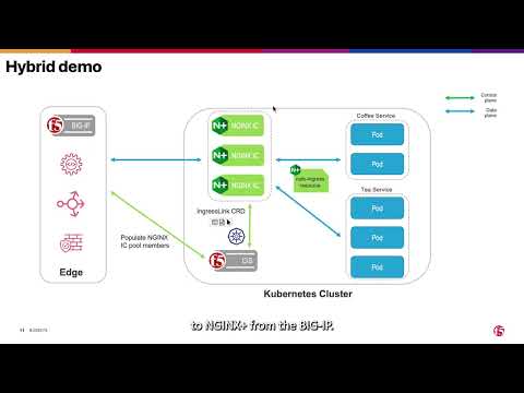 105Views3likes0Comments
BIG-IP Cloud-Native Network Functions 2.3: What’s New in CNF and BNK
Introduction F5 BIG-IP continues to advance BIG-IP Next for Kubernetes (BNK) and Cloud-Native Network Functions (CNFs) to meet the growing demands of service providers and modern application environments. F5 provides the full stack required to make cloud-native networking work in a service provider environment. CNFs alone are not enough; you need functions, control, infrastructure, and observability, working together as one system. What is new in BIG-IP Cloud-Native Network functions 2.3 for BNK and CNF? Release 2.3 adds MPLS provider edge support (early access), native UDP/TCP load balancing, DPU-accelerated data plane offload on NVIDIA BlueField, and subscriber-aware Policy Enforcement Manager (PEM) with Gx interface integration. It also introduces VRF-aware AFM policies, GSLB with Sync Groups for multi-region deployments, BBRv2 congestion control, and crash diagnostics that operate without host-level Kubernetes access. This release targets service providers and telecom operators who need cloud-native networking without sacrificing the protocol support and policy control of traditional infrastructure. Cloud-Native Network Functions (CNFs): What Changed in 2.3? In release 2.3, CNF capabilities focus on strengthening the underlying network functions required for service provider deployments. How does BIG-IP CNF 2.3 handle crash diagnostics in restricted Kubernetes clusters? Operating CNFs in production environments requires strong observability, even in restricted clusters. Release 2.3 introduces improvements to the crash agent that allow core files to be collected directly from pods without requiring host-level access. This enables deployments in more secure Kubernetes environments and simplifies troubleshooting when issues occur. How does BIG-IP CNF 2.3 operate in multi-tenant and multi-VRF environments? Multi-tenant environments demand precise control over traffic behavior. Release 2.3, Advanced Firewall Manager (AFM), introduces VRF-aware ACL and NAT policies, allowing operators to apply firewall and translation rules within specific routing contexts. This enables better segmentation and supports overlapping address spaces while maintaining consistent policy enforcement. It aligns CNFs more closely with how service provider networks are designed and operated. Can BIG-IP CNF 2.3 operate at edge? One of the most significant additions to this release is MPLS support within CNFs. This is currently an early-access feature and is expected to reach general availability in a future release. CNFs can now operate as provider edge nodes, supporting label-based forwarding and applying policies based on MPLS labels. This allows service providers to extend existing MPLS architectures into Kubernetes environments without requiring major redesigns. It also provides a path for replacing legacy systems with cloud-native alternatives while maintaining familiar networking constructs. UDP and TCP Application Load Balancing Release 2.3 expanded BNK support for high-performance UDP and TCP application load balancing, endtending traffic management capabilities beyond HTTP-based workloads. This enhancement enables support for a broader range of cloud-native applications, AI infrastructure traffic and telco protocols that rely on Layer 4 traffic patterns. Traffic can be intelligently balanced across services both inside and outside the Kubernetes cluster, which is critical for hybrid deployments and incremental modernization efforts. BNK deployed on NVIDIA DPUs has supported hardware offload capabilities since the Limited Availability (LA) release. With Release 2.3, advanced AI traffic optimization capabilities are now brought to General Availability (GA), including Intelligent AI Load Balancing, LLM Routing integration, Semantic Caching, and Token Governance. These capabilities help optimize AI inference traffic, improve GPU utilization, reduce latency, and enable more intelligent traffic steering across modern AI infrastructure environments. This enhancement is especially important for service providers and large enterprises operating mixed environments where traditional applications, AI workloads, and new cloud-native services must coexist. Organizations can modernize incrementally by introducing cloud-native components without requiring immediate architectural redesigns or disrupting existing applications. Subscriber-Aware Policy Enforcement Subscriber awareness remains a core requirement for service providers. Release 2.3 enhances Policy Enforcement Manager (PEM) with GX interface integration, enabling real-time policy enforcement based on subscriber data. This allows traffic to be classified and controlled dynamically, supporting use cases such as QoS enforcement, traffic shaping, and content filtering. It also enables compliance with regulatory requirements and opens new opportunities for service differentiation. Improved Observability and Aggregated Insights As CNFs scale, visibility becomes more complex. Earlier approaches relied on per-pod metrics, which made it difficult to build a unified view of the system. Release 2.3 enhances PEM by introducing aggregation through TODA, allowing statistics and session data to be collected and presented as a single entity. Enhancements to MRFDB and PEM reporting further improve visibility into subscriber sessions and traffic behavior, giving operators a more complete and centralized view of network activity. Building on this foundation, release 2.3 expands PEM capabilities with subscriber-aware policy enforcement. By integrating external policy systems and classification services, CNFs can now correlate traffic with subscriber identity and apply policies dynamically. This provides deeper insight into how individual subscribers and applications behave on the network, enabling more precise control and improved operational awareness. Additional DNS visibility enhancements, such as adding dig support into netkvest, further strengthen troubleshooting capabilities. By enabling more detailed DNS query inspection and response analysis, operators can quickly diagnose resolution issues and better understand traffic patterns tied to application behavior. Together, these enhancements move CNFs beyond basic monitoring. They provide a richer, more contextual understanding of traffic, subscribers, and services, which simplifies operations and enables faster troubleshooting in large-scale environments. DNS and Traffic Behavior Enhancements Release 2.3 includes improvements that address real-world network behavior, particularly in how DNS and transport protocols operate at scale. One example is the handling of DNS requests during certain scenarios. Instead of silently dropping traffic, CNFs can now return NXDOMAIN responses, preventing upstream systems from interpreting the lack of response as a service failure. This improves reliability and ensures better interoperability with external DNS resolvers in distributed environments. In addition, support for BBRv2 congestion control improves TCP performance in challenging conditions. It provides better fairness across flows and adapts more effectively to latency and packet loss, improving overall user experience in mobile and distributed networks. Extending to Multi-Region Traffic Management Release 2.3 continues to expand DNS capabilities with early access support for Global Server Load Balancing, enabling traffic distribution across multiple locations such as data centers and cloud environments. This represents an important step toward multi-region and hybrid architectures, where applications are no longer tied to a single cluster or deployment location. Building on this, the introduction of GSLB Sync Groups improves how configurations are managed across distributed deployments. Within a sync group, one instance is designated as the sync agent and is responsible for propagating configuration changes to other members. This approach ensures consistency across environments while preventing conflicting updates and reducing the risk of synchronization issues. Release 2.3 also begins to introduce more intelligent traffic steering with topology-based load balancing. This capability allows traffic to be directed based on user-defined parameters such as location or network proximity. As a result, operators can optimize application delivery by sending users to the most appropriate endpoint, improving latency and overall service quality. Together, these enhancements move CNFs closer to providing a fully cloud-native, globally distributed traffic management solution that aligns with modern application deployment patterns. What is new in BNK 2.3 for AI use cases? BNK 2.3.0 hardens and productizes key AI traffic optimization capabilities previously delivered through Early Access or iRules-based implementations, bringing them into native code for production-scale AI deployments while further expanding support for next-generation accelerated AI infrastructure. AI Traffic Optimization: Semantic AI Model Caching (GA) Reduces redundant GPU compute for similar or repeated prompts, improving token economics while lowering latency and increasing GPU efficiency for inference workloads. Intelligent AI Load Balancing (GA) Dynamically distributes AI inference traffic using real-time telemetry and infrastructure awareness to optimize GPU utilization, reduce queue bottlenecks, and improve response times. LLM Routing Integration (GA) Enables intelligent routing of requests across different LLMs and AI services based on policies such as cost, performance, model specialization, or operational requirements. Token Governance (GA) Provides visibility and control over token consumption with capabilities such as token monitoring, accounting, and rate limiting to help customers better manage AI infrastructure costs and tenant usage policies. AI Hardware Support Expansion: ConnectX-8 SuperNIC Support at x86 systems (GA) Expands BNK’s accelerated infrastructure support to next-generation NVIDIA networking platforms, enabling customers who are not yet ready to adopt DPUs to further optimize CPU efficiency and AI traffic processing performance. Beside CX-8, BNK 2.3.0 also supports CX-7s and BlueField-3 running in SuperNIC mode. BNK for Telco and Modern Applications Modern environments rarely consist of purely cloud-native applications. Most organizations are running a mix of legacy protocols, telco workloads, and newer microservices. Release 2.3 addresses this reality directly. One of the most important additions to this release is TCP and UDP load balancing. This extends BNK beyond HTTP-based traffic management and enables support for telco protocols and other non-HTTP workloads. It also allows traffic to be balanced both inside and outside the Kubernetes cluster, which is critical for hybrid architectures and phased migrations This capability reflects a broader shift in BNK. It is no longer just an ingress layer. It is evolving into a unified traffic management platform that can handle diverse protocols and application types without forcing architectural changes. For service providers, this means they can modernize incrementally. Existing applications can continue to operate while new components are introduced in Kubernetes. For enterprise environments, it provides a consistent way to manage traffic across distributed services without introducing additional tools or complexity. What’s new in BNK 2.3 for modern apps & telcos? Multi-Tenant Debugging (RBAC-secured Debug API) We added a new Debug-API that uses the Kubernetes RBAC (Role-Based Access Control) to allow running debug commands according to defined permissions. The administrator can assign rules (Administrator, Operator, Tenant) to users. This allow or deny users to run debug commands according to their rule and creates separation between Namespace Tenants to limit the user access to their Namespace only. Grafana Sample Dashboard Template We created a detailed instruction document that describes the setup of Prometheus and Grafana for Multi Tenancy support. With that the customer can configure his own Dashboards to display the tenant stats and separate the display so each tenant can view its own. The customer can create its own Dashboards based on the samples. Each Namespace Tenant can view its own statistics only. Gateway API Conformance Improvements BNK’s development has largely been more focused on adding functionality to expand the Gateway API than on conformance with existing use cases. Gateway API Security Enhancement (Namespace-based FW) When working in Kubernetes, serving to isolate tenancy using namespace it is valuable to be able to create namespace-based firewall rules. With our isolation of tenancy, customers do not want to have separate tools for east-west (Kubernetes network policies) and north-south (firewall); we unify their security controls. Gateway API: Load Balancing External Resources BNK’s Gateway API routes are being extended to specifically cover load balancing to external endpoints. This can either leverage the Kubernetes concept of an “endpoint slice” or using the F5 “F5pool” CRD. Because external endpoints aren’t probed by Kubernetes, BIG-IP monitors are enabled for these Gateway routes. TMOS Integration: DNS (aka GTM/GSLB) Coordinate external DNS (GTM/GSLB) BIG-IP with BNK; publish/remove ingress VIPs as BIG-IP TMOS DNS Service WideIP pool members with automatic WideIP pool member enable/disable based on K8s service availability. This feature allows multi-tiered deployments with global service availability. BNK Integration with Openshift Platform Previously, the only Openshift-specific functionality in BNK was support for the OVN CNI (via Multiple External Gateways (MEG) feature). With this new work, FLO will support being used via an Openshift operator hub (initially private instance, until business/partner items worked out) and Openshift routes are translated to BNK Gateway objects. Gateway API: IPAM Support (Infoblox) Previously, we integrated the F5 IPAM controller with BNK for Gateway API. That IPAM now can leverage Infoblox, which is used by BNPP (and was a feature of the original IPAM controller, as leveraged by CIS). Proxy Protocol Support Our customer uses proxy protocol with BIG-IP to serve their applications. To migrate to BNK, they required similar support. Under the covers, this is enabled with an iRule, but that iRule is hidden from the customer. Active-Standby Interface Bonding Currently, having the node use LACP and applications like BNK use DPDK separately causes problems. This method is meant to allow the Linux host to control active links, leveraging a “floating MAC address”. Limited Availability/EA: IBM Cloud ROKS Support This initiative prioritizes support in IBM cloud. The feature is LA in this release and Future releases will GA the use of IBM Cloud with ROKS. Early Access: BNK Support for AWS/EKS Early access support for AWS/EKS – this should be used for F5-led demonstration, not for direct-to-customer deployment. First step toward Public Cloud support in AWS/EKS. Frequently asked questions These questions represent the most common queries architects and operators ask when evaluating BIG-IP Cloud-Native Network Functions 2.3. Q: What is new in BIG-IP Cloud-Native Network Functions 2.3? A: BIG-IP CNF 2.3 adds MPLS provider edge support (early access), native UDP/TCP load balancing, DPU-accelerated data plane offload on NVIDIA BlueField, subscriber-aware PEM with Gx integration, VRF-aware AFM policies, GSLB with Sync Groups, congestion control, and crash diagnostics that operate without host-level Kubernetes access. Q: What CPU savings does BNK on NVIDIA BlueField DPU deliver? A: Validated testing (Tolly Report #226104, February 2026) showed approximately 80% host CPU reduction, 40% more output tokens per second versus HAProxy on Llama 70B, and 61% faster time to first token (TTFT). These results reflect BNK offloading data plane processing from the host CPU to the BlueField DPU, freeing the host compute for application workloads. Q: Does BIG-IP CNF 2.3 support protocols beyond HTTP and HTTPS? A: Yes. Release 2.3 adds native UDP and TCP load balancing to both CNFs and BNK, extending traffic management beyond HTTP. This supports telco protocols such as GTP-U, Diameter, and RADIUS, with the ability to balance traffic across services inside and outside the Kubernetes cluster.246Views1like0Comments


