cloud
4004 TopicsUsing eBPF Filters to Capture and Inspect BIG-IP CNE CNF Traffic
Introduction In this article we go through integrated setup with both F5 BIG-IP eBPF Observability (EOB) and F5 BIG-IP Cloud-Native Edition (CNE) CNFs. In our lab we go through deploying BIG-IP EOB and start capturing client traffic within cnf-fw-01 namepsace. Capturing the traffic in this cloud-native architecture is as easy as creating the directive which automatically creates the streams and show the live capture. Step by Step deployment This video walks us through deploying the BIG-IP EOB through openshift operators hub, then creating the required directive to capture the client processed traffic and show it over BIG-IP EOB dashboard. Related Content F5 BIG-IP eBPF Observability (EOB) Deployment walkthrough | DevCentral eBPF Observability for Kubernetes & Cloud-Native Apps BIG-IP eBPF Observability (EOB) deployment walkthrough 50Views1like0Comments
ADC01 – Weak DNS Practices
Introduction DNS is often the unsung hero of application delivery, quietly humming along until something goes wrong. This cornerstone of internet infrastructure translates human readable domain names into machine friendly IP addresses, bridging the gap between users and applications. While vital, DNS frequently gets overlooked, leading to unforeseen performance, availability, scalability, and security issues in application delivery. In today's interconnected world, where seamless application delivery is critical across industries such as finance, healthcare, insurance, telecommunications, hi-tech, energy, government, retail and e-commerce, automotive, and manufacturing, weak DNS practices can wreak havoc. Since stakes are high and user expectations demand near instantaneous responsiveness and reliability, the principles discussed here apply universally. Businesses in any sector must recognize DNS as more than just a basic utility because it is a foundational layer of their application delivery strategy. AI Reference Architecture Use Case example: Enhancing DNS Security and Performance with F5 BIG-IP To better understand how optimized DNS practices strengthen application delivery, let’s consider the following real world use case: Steps in the DNS Optimization Process: Client Initiates DNS Query: A client, located on the external network, initiates a DNS query to resolve a domain name. Query Passes Through F5 BIG-IP: The F5 BIG-IP acts as a secure DNS proxy, validating the query and applying DNSSEC (Domain Name System Security Extensions) for added cryptographic security. DNSSEC ensures that queries are not tampered with and originate from a legitimate source. Authoritative DNS Responds: The validated query is routed securely to the authoritative DNS server cluster within the internal network. The authoritative DNS responds with the appropriate IP address. Response Returned to Client: The optimized, secure response is returned to the client with minimal latency, leveraging DNSSEC and optimized TTL (Time-to-Live) settings for better user experience. This workflow illustrates how incorporating F5 BIG-IP into your DNS architecture can enhance application security, scalability, and performance. Consequences of Weak DNS Practices Impact on Performance DNS inefficiencies are a hidden bottleneck for application performance. In 2023, nearly 27% of user complaints about poor application performance stemmed from DNS related slowdowns (Auvik). When DNS servers aren’t optimized or critical security features like DNS Security Extensions (DNSSEC) are absent, the impact cascades across application performance: Latency increases: Low TTL (Time-to-Live) settings overload DNS servers with repeated queries, slowing down responses for users spread across regions. Vulnerability to hijacking: Without DNSSEC, attackers can intercept or redirect traffic to slower or malicious servers, significantly impacting response times and user experience. Impact on Availability DNS disruptions, either due to attacks or misconfigurations, can lead to major availability issues. For instance: DNS hijacking or cache poisoning: Attackers inject fake records into DNS servers, redirecting users to harmful websites. Without DNSSEC, these vulnerabilities remain exploitable, leading to user mistrust. Low or mismatched TTL settings: These settings exacerbate availability problems by overwhelming DNS servers during failovers or scaling events, making applications inaccessible during critical times. Cloud-based global applications, which rely on dynamic DNS updates to remain accessible, worsen the problem when DNS configurations cannot keep pace with the scaling requirements of infrastructure. Impact on Scalability Scalability is a fundamental goal for any global application. Yet, weak DNS practices create bottlenecks: Dynamic DNS updates: Insecure or improperly authenticated dynamic DNS updates disrupt routing, crippling the application’s ability to handle increased user demand. Unprepared DNS infrastructure: With global audiences and fluctuating traffic volumes, under-provisioned or misconfigured DNS servers can experience elevated latency and outages, hindering business growth and reducing global reach. Impact on Operational Efficiency Operational inefficiencies arise from frequent DNS queries (due to low TTLs) and insecure configurations. IT teams become mired in troubleshooting and responding to incidents like DDoS attacks, instead of focusing on broader strategic goals. Moreover, the resources directed toward mitigating DNS-related issues inflate operational costs unnecessarily, wasting valuable time and money. The Undeniable Need for Best Practices To avoid these pitfalls, organizations need to prioritize robust DNS architectures. Here are key practices to implement: DNSSEC for Security DNSSEC (Domain Name System Security Extensions) operates as a safeguard against cache poisoning and DNS hijacking attacks. Implementing DNSSEC ensures the cryptographic validation of DNS records, mitigating risks from unauthorized changes. This adds a layer of trust and reliability to your DNS infrastructure and by extension to user experiences. DNSSEC is no longer a luxury, but a necessity for securely connecting users across the globe. Optimized TTL Settings for Balance TTL settings determine how long DNS information is cached by resolvers before they query authoritative DNS servers. Too short a value results in frequent DNS lookups, increasing server load and latency. Conversely, excessively long TTL values cause outdated information during dynamic scaling. Organizations should analyze traffic patterns and application behavior to strike the right balance. Regular revisions of TTL settings ensure that user queries are routed efficiently without bottlenecking operations. Secure Dynamic DNS Update Dynamic DNS updates are essential for cloud-based infrastructures where IP addresses frequently change. However, insecure update mechanisms are a gold mine for attackers, providing opportunities to alter DNS records maliciously. By using authentication and encryption mechanisms for DNS updates, organizations can protect records and optimize routing seamlessly. Distributed DNS Architecture Relying on a single DNS service provider or a centralized DNS setup increases the risks of downtime. By spreading DNS across multiple geographically independent providers and locations, organizations ensure better fault tolerance and reliability. Global Implications of Weak DNS In 2023, 90% of organizations faced DNS attacks, with financial losses averaging $1.1 million per incident (EfficientIP). These attacks are not just a cost center but also a real time disruption that tarnishes brand reputation and user trust. Each organization encounters an average of 7.5 DNS attacks annually, underlining the broad spectrum of vulnerabilities across industries. Global operations are particularly susceptible to DNS misconfigurations and weaknesses. Whether through hijacking traffic, launching DDoS campaigns, or exploiting TTL mismanagement, attackers leverage DNS vulnerabilities to cripple applications and compromise sensitive data. To scale securely, organizations need DNS practices aligned with industry standards, steering away from outdated configurations or reliance on "default" infrastructure. Final Thoughts Weak DNS practices are a silent killer of application performance, availability, scalability, and operational efficiency. The good news? These challenges are entirely avoidable. By implementing DNSSEC, optimizing TTL settings, securing dynamic DNS updates, and adopting distributed DNS strategies, organizations can dramatically reduce these risks. In the digital landscape of today, where milliseconds can dictate millions in revenue, DNS cannot be an afterthought. It must be a core pillar of application delivery strategies, ensuring that every user query is answered rapidly, reliably, and securely. DNS influences every aspect of the user experience. It’s the first impression your application makes. Don’t squander it. As your applications scale to meet global demand, strong DNS practices will ensure they deliver consistently, no matter where users click “Buy Now.” Reference Articles Scaling, Securing, and Optimizing DNS Hyperscale and Protect Your DNS While Optimizing Global App Delivery Intelligent DNS Firewall for Service Providers F5 DNS: Global Server Load Balancing The Application Delivery Top 10 ADSP Platform overview AI reference architecture The BIG-IP GTM: Configuring DNSSEC Configuring BIG-IP for Zone Transfer and DNSSEC107Views0likes0CommentsEffective Traffic Management: Addressing ADC04's Insufficient Traffic Controls
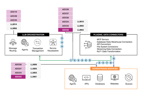
Applications today face unprecedented demand variability, requiring organizations to prioritize effective traffic management to ensure a seamless user experience. ADC04, one of the key challenges in application delivery per F5's "Application Delivery Top 10," highlights insufficient traffic controls. This issue plagues high-demand environments across industries such as e-commerce, healthcare, high-tech, automotive, insurance, and more, leading to performance bottlenecks, reduced availability, inefficiencies, and scalability challenges. Let's discuss the implications and solutions for this issue, with an added use case to demonstrate practical implementation. AI Reference Architecture The Challenge of Insufficient Traffic Controls Modern digital ecosystems experience fluctuating traffic volumes due to use cases like e-commerce promotions, flash sales, or API-driven workloads. For example, an e-commerce API could go from handling hundreds of requests per second (RPS) to thousands or more during promotional events. Without proper rate limiting, throttling, or caching mechanisms, public APIs become vulnerable to overburdened backend services, Distributed Denial of Service (DDoS) attacks, and inefficient scaling. Automated processes, such as analytics workloads, CI/CD deployments, and backups, exacerbate uneven workloads on backend systems. Furthermore, modern AI applications with data-intensive processing introduce yet another layer of complexity, requiring sophisticated traffic controls. The Consequences of Inefficient Traffic Controls Performance Issues Excessive traffic without sufficient controls leads to backend overload, degrading application response time. For example: User Frustration: Slow response times result in poor customer experiences, where 70% of shoppers abandon purchases due to delays. Critical Application Failures: In AI use cases, such as real-time conversational bots, processing delays impact outcomes and user trust. Reduced Availability API services lacking rate limiting and traffic throttling are especially prone to DDoS attacks or service outages. Additionally, backend systems may face resource starvation due to unoptimized caching mechanisms, reducing availability even during normal traffic conditions. Limited Scalability Applications unable to intelligently manage traffic flows struggle to handle unexpected traffic spikes. Inefficient caching and chaotic workload distribution limit the capacity to scale dynamically. Operational Inefficiencies The absence of automated traffic controls forces manual monitoring and intervention during traffic surges. High operational overhead and inefficient resource usage affect cost-effective management of infrastructure. Use Case example: Implementing Traffic Controls for an E-Commerce Public API The diagram below illustrates a practical implementation of traffic controls using advanced Application Delivery Controller (ADC) features (e.g., BIG-IP Local Traffic Manager) for an e-commerce public API. While tailored for e-commerce, these are equally applicable to other industries, such as finance, insurance, high-tech, and automotive. Key Features for Effective Traffic Management: Global Rate Limiting: Enforces a cap on total requests per second (RPS) to avoid backend overload. Per-API Key Throttling: Limits RPS at an API key level (e.g., 100 RPS per user), ensuring fair usage. CAPTCHA Trigger: Introduces CAPTCHA challenges for clients exceeding predefined limits to mitigate abuse. Circuit Breaker Logic: Detects faults in backend API servers and reroutes traffic to stable instances where possible. Traffic Forwarding or Rejection: Directs healthy requests to backend API servers and rejects problematic traffic. Comprehensive Logging and Metrics: Logs control events, such as rate-limit breaches or circuit-break activations, and streams them into observability platforms like ELK, Prometheus, or Datadog for dashboards and automated alerts. Functionality Overview Clients Send API Requests: Public API clients interact with the ADC (BIG-IP LTM), where all incoming requests are initially processed. Rate Limiting and Key Enforcement: The ADC enforces global rate limits and per-client throttling policies to avoid overloading backend servers. Action on Violations: Requests breaching limits trigger appropriate actions—delays, CAPTCHAs, or outright rejection. Health-Check Monitoring: The ADC regularly monitors backend API servers for faults and dynamically reroutes traffic to healthy nodes using circuit-breaker policies. Logs and Metrics Streaming: All traffic patterns, rule activations, and violations are logged and streamed to observability platforms for operational transparency. Best Practice Recommendations for Traffic Controls Rate Limiting and Throttling Global and per client rate limits are critical for protecting backend services during demand surges. For example: Put a 100 RPS cap per API key. Differentiate limits for premium services or geographies where critical workloads demand higher quality of service. Intelligent Caching Caching reduces backend load by offloading repetitive requests: Use semantic and edge caching for dynamic workloads like AI APIs. Adopt adaptive caching mechanisms to handle variable traffic patterns and reduce latency. Circuit Breaker Logic Circuit breakers prevent cascading failures in the API ecosystem by rerouting traffic to healthy systems: Monitor backend server health dynamically. Use adaptive retry mechanisms to minimize disruptions. Observability and Logging Real-time logging and monitoring tools like ELK or Prometheus provide insights into API performance: Set up custom dashboards to monitor API health, rate-limit violations, and traffic loads. Automate alerts for anomalies (e.g., high latency or recurring limit breaches). Conclusion As demonstrated by the use case, robust traffic controls are essential for managing fluctuating workloads, ensuring availability, and optimizing operational efficiency. Layered controls such as rate limiting, advanced caching, and circuit breaker mechanisms enforce resilience and scalability. Integrating observability tools ensures transparency and rapid issue resolution in real time. With insufficient traffic controls identified as a major challenge, adopting these strategies is crucial for long-term API operational success, particularly for high-traffic environments across industries such as e-commerce, finance, insurance, high-tech, and automotive. Reference Article Managing Traffic with Bandwidth Controllers Intelligent Traffic Management with the F5 BIGIP Platform Mitigating OWASP API Security Risks: Unrestricted Resource Consumption using BIG-IP iRule::ology - Table Based Rate Limiting AI reference architecture ADSP Platform overview The Application Delivery Top 1062Views1like0CommentsADC02 – Lack of Fault Tolerance & Resilience in Enterprise Applications Using A2A Protocol
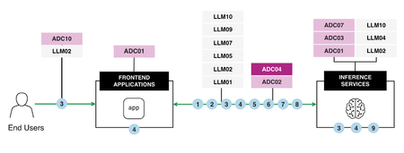
Introduction In the world of enterprise applications, fault tolerance and resilience play a central role in ensuring uninterrupted service delivery. However, the absence of these critical components can lead to degraded performance, downtime, costly inefficiencies, and dissatisfied users. This article explores fault tolerance challenges using the A2A protocol in enterprise applications, leveraging F5 BIG-IP to resolve primary data center failures, as illustrated in the attached diagram. AI Reference Architecture The Use Case at a glance The architecture for this scenario involves: AI Clients initiating A2A traffic routed via a Primary BIG-IP LTM. The Primary BIG-IP LTM processes the requests and routes intelligently based on A2A protocol inspection. In the event of a Primary BIG-IP failure, a Standby BIG-IP LTM in a high availability (HA) configuration takes over seamlessly. AI Agents (hosted across multiple instances) process user traffic through the Active BIG-IP, ensuring continuous service availability. This structure ensures resilience while avoiding performance bottlenecks caused by load imbalances or failures. Consequences of a Lack of Fault Tolerance and Resilience Impact on Performance Without adequate fault tolerance mechanisms: Failures in a primary system increase the load on remaining servers, causing degraded response times. Systems experience 35% more downtime during high-load scenarios, as indicated by LoadView’s 2024 network performance report. Impact on Availability A lack of redundancy or failover capabilities results in prolonged downtime when a failure occurs, tarnishing organizational reputation and eroding user trust. In complex environments, cascading failures can be triggered, amplifying the chaos. Impact on Scalability Systems lacking fault tolerance cannot scale dynamically to meet changing traffic demands. Rapid traffic surges overwhelm resources, causing bottlenecks. Overprovisioning as a stopgap becomes costly and inefficient. Impact on Operational Efficiency When failures occur, manual interventions become necessary, which increase operational overhead, downtime, and costs. Automated mechanisms for failover and load balancing are critical in reducing reliance on human intervention and ensuring operational efficiency. Solutions to Enable Fault Tolerance and Resilience Using F5 BIG-IP Load Balancing with BIG-IP F5 BIG-IP's iRules dynamically route A2A traffic, ensuring intelligent management even in volatile conditions. A load balancing configuration includes: Active-Standby Configuration: Load balancing redirects traffic to the standby BIG-IP in case of failure. Active-Active Configuration (Optional): For consistently high traffic volumes, active-active HA ensures even traffic distribution, improving both availability and scalability. High Availability (HA) Setup BIG-IP’s HA architecture supports synchronized active and standby systems: Failover Objects and Floating IPs allow seamless rollover during primary system failures. Redundant servers prevent single points of failure, ensuring uninterrupted operations. Comprehensive Health Monitoring Advanced health checks go beyond simple pings to assess the full responsiveness and integrity of applications and supporting infrastructure: Use distributed health checks from geographically disparate locations to simulate actual user experiences. Create application-specific health checks to test backend systems fully. Programmable Infrastructure Programmable infrastructure with F5 BIG-IP allows organizations to: Customize fault-tolerance strategies tailored for specific applications. Adjust traffic dynamically in real-time using programmable application delivery controllers (ADCs). Automation for Instant Response By integrating failover automation, organizations can: Detect and mitigate failures faster, reducing downtime. Lower operational overhead by minimizing manual interventions. Best Practices for Fault Tolerance Optimization Readiness Planning Use resources like "BIG-IP HA - Do it the Proper Way" to correctly implement HA configurations. Synchronize configurations and session data between BIG-IP devices. Tailored Load Balancer Configurations Optimize load balancing policies for real-world traffic patterns. Implement automated traffic redirection during outages. Proactive Monitorin Constantly monitor application performance via distributed health checks described in the "F5 Academy - BIG-IP HA - Do it the Proper Way". Resilience Testing Periodically test failover functionality to ensure system readiness to handle failures under real-world conditions. Resource Scalabilit Leverage the F5 Active-Active HA Configuration for highly scalable environments. Why Fault Tolerance Matters Fault tolerance isn’t just a technical concept; it directly dictates application availability, performance, and scalability. Proactive strategies like HA, programmable infrastructure, and automation enable organizations to build resilient systems capable of handling any disruptions. Conclusion In the ever-evolving digital landscape, resilience and fault tolerance are no longer optional—they are imperative. Leveraging F5 BIG-IP solutions for HA, intelligent load balancing, and failover mechanisms ensures applications remain available, scalable, and efficient, even during disruptions. By building fault-tolerant systems, enterprises not only meet today’s challenges but also position themselves for future growth and stability. Learn More Explore these resources to dive deeper into enabling fault tolerance and resilience: Intro to: BIG-IP HA - Do it the Proper Way High availability on F5 BIG-IP load balancers F5 BIG-IP HA Active Standby Configuration F5 Active-Active HA Configuration F5 Academy - BIG-IP HA - Do it the Proper Way ADSP Platform overview AI reference architecture The Application Delivery Top 1063Views1like0CommentsF5 Distributed Cloud – Unit and Integration tests with Terraform
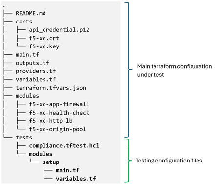
Introduction The Terraform test framework provides module authors with an integrated way to run unit and integration tests. It verifies that code changes do not introduce breaking behavior before production rollout. Terraform test prevents any risk on the existing state or infrastructure by keeping the state file in memory as an ephemeral entity. It never writes to a terraform state file, ensuring tests run completely separate from regular plan or apply workflows. The framework supports two testing models: Unit Testing: Runs a terraform plan to validate custom logic, calculations, and input conditions without provisioning real resources. This mode is fast, free, and runs entirely in memory. Integration Testing: Runs terraform apply to create temporary infrastructure, perform assertions against live resources, and automatically destroy those resources when the test completes. By default, test runs use command = apply, so integration testing creates real infrastructure and validates behavior against those deployed resources. To perform unit testing without creating infrastructure, you can override this behavior by setting the command attribute in a run block to plan. Configuration The following example shows a directory structure for terraform native tests: The main terraform configuration is based on the WAAP protected HTTP applications example: https://github.com/f5devcentral/f5-professional-services/tree/main/examples/f5-distributed-cloud/terraform/f5-xc-terraform-test. The compliance.tftest.hcl includes the logic to validate the following test cases: Check Compliance Run block Validate that a required Service Policy is inherited from the namespace if the Load Balancer is advertised on the public network and the origin server is behind a Customer Edge (CE) Security service_policy Validate that a required Service Policy is applied directly to the Load Balancer if it is advertised on the public network and the origin server is behind a CE Security service_policy Check that an App Firewall policy is applied to the HTTP Load Balancer if it is advertised on the public network Security app_firewall Verify that the Load Balancer name complies with the RFC 1035 Domain Names. Naming Governance http_load_balancer_name Verify that the HTTP Load Balancer quota is not exceeded. Resource governance quota_usage A helper module is included for managing test-specific resources such as data sources. It uses F5 Distributed Cloud Services API to get current quota usage for HTTP Load Balancers and the active namespace Service Policies: # setup module # Fetch data from a REST API data "http" "xc_quota_usage" { url = "${var.api_url}/web/namespaces/system/quota/usage" request_headers = { Accept = "application/json" } client_cert_pem = file(var.f5-xc_cert) client_key_pem = file(var.f5-xc_key) } data "http" "xc_active_sp" { url = "${var.api_url}/config/namespaces/${var.namespace}/active_service_policies" request_headers = { Accept = "application/json" } client_cert_pem = file(var.f5-xc_cert) client_key_pem = file(var.f5-xc_key) } # Use the response locals { xc_quota_usage = jsondecode(data.http.xc_quota_usage.response_body) xc_active_sp = jsondecode(data.http.xc_active_sp.response_body) } Below is the outputs.tf file for the module: output "xc_quota_usage" { value = { "HTTP" = local.xc_quota_usage.objects.http_loadbalancer.usage.current } } output "xc_active_sp" { value = local.xc_active_sp.service_policies[*].name } The variables.tf file used by the module is shown below: # setup module variables variable "tenant" { default = "<tenant_id>" } variable "api_url" { default = "https:// <tenant_name>.console.ves.volterra.io/api" } variable "f5-xc_cert" { default = "./certs/xc.crt" } variable "f5-xc_key" { default = "./certs/xc.key" } variable "namespace" { default = "default" } The main test file included in the test directory, compliance.tftest.hcl, contains the test logic within run blocks that applies a terraform “plan” or “apply” command to perform assertions on the resulting state: # compliance.tftest.hcl run "global_setup" { # This block initializes a module to fetch information required # for testing. module { source = "./tests/modules/setup" } } run "service_policy" { command = plan variables { required_service_policies = "allow-vpn-ip-demo-sp" } # Check that a required Service Policy is inherited from the # namespace if the Load Balancer is advertised on the public # network and the origin server is behind a CE assert { condition = ( module.http-lb.app_lb_default_vip == false ? true : module.origin.private_origin == false ? true : (module.http-lb.app_lb_ns_service_policies == false ? true : contains(flatten(run.global_setup.xc_active_sp), var.required_service_policies)) ) error_message = "Service Policy \"${var.required_service_policies}\" must be associated with Load Balancer ${module.http-lb.app_lb_name} or inherited from the namespace." } # Check that a required Service Policy is applied directly to the # Load Balancer if it is advertised on the public network and the # origin server is behind a CE assert { condition = ( module.http-lb.app_lb_default_vip == false ? true : module.origin.private_origin == false ? true : (module.http-lb.app_lb_ns_service_policies == true ? true : contains(flatten(module.http-lb.app_lb_active_service_policies), var.required_service_policies)) ) error_message = "Service Policy \"${var.required_service_policies}\" must be explicitly associated with Load Balancer ${module.http-lb.app_lb_name} or inherited from the namespace." } } run "app_firewall" { command = plan # Check that an App Firewall policy is applied to the HTTP Load # Balancer if it is advertised on the public network assert { condition = module.http-lb.app_lb_default_vip == false ? true : length(module.http-lb.app_lb_app_firewall) > 0 error_message = "An App Firewall must be associated with Load Balancer ${module.http-lb.app_lb_name} if advertised on Internet " } } run "http_load_balancer_name" { command = plan # Check that the Load Balancer name is correct assert { condition = can(regex("^[a-z]([-a-z0-9]*[a-z0-9])?$", local.http-lb-name)) && length(local.http-lb-name) <= 63 error_message = "The resource name must be a valid DNS-1035 label: 1-63 lower-case alphanumeric characters or '-', starting with a letter and ending with an alphanumeric character." } } run "quota_usage" { command = plan # Check that the HTTP Load Balancer quota is not exceeded assert { condition = run.global_setup.xc_quota_usage["HTTP"] <= 200 error_message = "HTTP Load Balancer quota exceeded" } } The assert blocks within each run block define conditions that must evaluate to true for the test to pass. Running the tests 1. Initialize Terraform configuration. To run the tests, the Terraform workspace needs to be initialized to configure the backend and install all providers and modules referred to in the configuration (main and test): 2. Running the initial test When the terraform test command is executed, it scans the current root directory ./ and the subdirectory ./tests/ for files with .tftest.hcl or tftest.json extensions. To overwrite the default discovery behavior, the following command line flags can be used: Behavior Flag Example Change the testing directory test -test-directory terraform test -test-directory=integration-tests Run a specific test file filter terraform test -filter=tests/validation.tftest.hcl This is the main tfvars file, used to validate the run blocks { "tenant": "<tenant_id>", "api_url": "https://<tenant_name>.console.ves.volterra.io/api", "api_p12_file": "./certs/api_credential.p12", "f5-xc_cert": "./certs/xc.crt", "f5-xc_key": "./certs/xc.key", "base": "demo-app", "namespace": "demo", "domains": ["demo-app.demo.net"], "origin_servers": [ { "origin": "1.2.3.4", "site": "", "virtual_site": "onprem-demo-vs", "network": "inside" }, { "origin": "5.6.7.8", "site": "", "virtual_site": "onprem-demo-vs", "network": "outside" } ], "environment": "prod", "waf_policy": true, "service_policy": [ { "name": "allow-vpn-ip-demo-sp", "namespace": "shared" }, { "name": "allowed-sources-demo-sp", "namespace": "demo" } ], "origin_pool_port": 80, "use_tls": false } When all the assertions in the execution block pass, the test is considered successful 3. Validation of assertions 3.1. Unit testing To perform unit testing, the tests can be executed using the command = plan attribute. Setting the command to plan forces Terraform to only generate an execution plan and validate your configuration logic without creating real cloud resources, making the process fast and safe. Example 1: The required Service Policy is not active in the namespace, the Load Balancer is configured with the default setting to apply namespace policies, it is advertised on the public network, and the origin server is behind a CE. Service Policy "allow-vpn-ip-demo-sp" service policy is not in the namespace Active Service Policies: Example 2: The required Service Policy is not associated with the Load Balancer when a specific list of Service Policies is applied, it is advertised on the public network, and the origin server is behind a CE. Service Policy "allow-vpn-ip-demo-sp" service policy is removed from the tfvars file: Example 3: Verify that an App Firewall policy is applied to the HTTP Load Balancer if it is advertised on the public network. To force this test to fail, the waf_policy variable is set to false in the tfvars file: Example 4: Verify that the HTTP load balancer name conforms with the core RFC DNS 1035 rules. To force this test to fail, a period is added to the base variables in terraform.tfvars.json: Example 5: Verify that the HTTP load balancer quota has not been exceeded. To force this test to fail, a value lower than the current quota is added to the condition: 3.2. Integration testing To perform integration tests, we can run them using the command = apply attribute. By setting the command as apply, Terraform provisions real infrastructure, runs the assertions against the live resources and then automatically destroys them. Example: The required Service Policy is not active in the namespace, the Load Balancer is configured with the default setting to apply namespace policies, it is advertised on the public network, and the origin server is behind a CE. Service Policy "allow-vpn-ip-demo-sp" service policy is not in the namespace Active Service Policies: The ephemeral resources are created: The audit log entries record the creation and deletion of resources: Conclusion The native terraform test framework offers a secure and unified way to validate F5 Distributed Cloud Services Infrastructure by operating against test-specific, short-lived resources. This lets you detect breaking changes early and use the assertions as built-in guardrails, ensuring infrastructure code quality without complex external dependencies.193Views0likes0Comments
F5 Rules for AWS WAF - does F5 have any access to the request data inspected by the rule groups?
I'm reviewing the data handling characteristics of the F5 Rules for AWS WAF managed rule groups (purchased through AWS Marketplace) and would like to confirm my understanding with the community. K21015971 describes the procedure for reporting a suspected false positive. As I read it, the customer is asked to log the blocked HTTP requests along with the names of the rules that matched, mask any sensitive information with ****, and then submit a question with the F5 rules for AWS WAF tag and attach those requests. My reading of that procedure is that F5 has no independent access to the requests inspected by the rule groups. If F5 could see them, there would be no need for the customer to extract, mask and attach them manually. Is that reading correct? More specifically, could someone confirm whether the following are accurate? 1. HTTP request data inspected by the rule groups (source IP addresses, headers, request bodies, query strings, cookies) is never transmitted to F5. 2. AWS WAF logs, sampled requests, CloudWatch metrics, and the labels generated by rule matches remain entirely within the subscriber's own AWS account, with no access path available to F5. 3. The only information F5 receives in connection with a subscription is AWS Marketplace billing and metering data. One related question. Section 5 of the F5 End User License Agreement (Collection and Use of Product Information) notes that, depending on the product and the licensed pricing tier, a customer may be able to opt out of the collection and use of such information by configuring the product to disable those features. Is there any such configuration available for these rule groups? Or does the question simply not arise because no collection takes place for this product? Thanks in advance.34Views0likes0CommentsF5 XC WAF Automation for Bulk IP Prefix Blocking
I've a requirement to block more than 5,000 IP addresses in F5 Distributed Cloud (XC) WAF. Is there any supported option to automate the creation or update of IP Prefix Sets using scripts or APIs, instead of adding the prefixes manually through the UI? The goal is to automate the process of importing and maintaining the IP prefixes used for blocking traffic. Thank you.97Views0likes2CommentsADC03: Incomplete Observability – A Critical Application Delivery Challenge
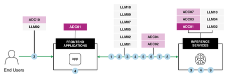
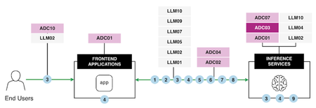
Observability is the backbone of modern application delivery, enabling the detection of performance issues, analyzing system usage, and monitoring overall health. However, Incomplete Observability, characterized by insufficient logging, inadequate monitoring tools, and inconsistent data collection, introduces significant business risks. These risks range from limited visibility into performance bottlenecks and prolonged service disruptions to flawed scaling decisions and inefficient operations. To address these challenges effectively, it is crucial to understand the core issues at hand and implement robust strategies and tools, such as F5 BIG-IP and OpenTelemetry, that enhance observability across the infrastructure. Let's explore the impacts of Incomplete Observability and practical solutions, incorporating lessons from a real-world use case. AI Reference Architecture In an AI-powered application ecosystem, observability plays a pivotal role in coordinating and monitoring interactions between end users, frontend applications, and inference services. The following AI Reference Architecture diagram illustrates a typical flow: Diagram Overview: End Users initiate requests through frontend applications. These applications connect with backend Large Language Models (LLMs) based on user-specific needs. Inference Services operate at the core, processing data to deliver accurate and efficient results. Monitoring critical pipelines ensures reliability and scalability while maintaining secure data flows. By aligning observability with such an architecture, AI systems can handle complex pipelines effectively, optimizing performance, security, and governance. Consequences of Incomplete Observability Impact on Performance The absence of complete observability limits an organization’s ability to proactively detect and resolve performance bottlenecks. Without detailed insights into key metrics like latency, response times, and resource utilization, it becomes nearly impossible to identify root causes or improve application responsiveness. For example, undetected spikes in CPU or memory usage can lead to degraded user experiences and even system crashes. Impact on Availability Incomplete observability hampers availability—an essential component of application delivery. Downtime and overlooked critical failures are costly, with 32% of organizations reporting an average outage cost exceeding $500,000 per hour (New Relic). For distributed systems, limited visibility can cause cascading failures, with a minor issue in one system component triggering widespread service interruptions before being detected. Impact on Scalability Dynamic and scalable infrastructure is essential for supporting modern applications with variable workloads. Incomplete observability creates significant obstacles in tracking traffic trends and resource utilization accurately, leading to resource under-provisioning or over-provisioning that wastes budgetary resources or results in outages. Impact on Operational Efficiency Operational inefficiencies arise when IT teams are forced to sift through fragmented, inconsistent data sets to identify issues. Logs spread across incompatible formats or disconnected tools lead to delays in troubleshooting and limited optimization opportunities. This reduces teams' ability to respond to incidents promptly and improve overall system performance. Best Practices for Overcoming Observability Gaps F5's BIG-IP and OpenTelemetry address these challenges by delivering end-to-end observability capabilities requiring real-time insights into application health, performance bottlenecks, and operational metrics. These tools facilitate timely root cause analysis and enable proactive management of distributed systems. Enhanced Observability Framework: Use Case Overview The following diagram illustrates a practical implementation of comprehensive observability using tools like F5 BIG-IP and OpenTelemetry: Use Case Breakdown Consolidate Traffic via F5 BIG-IP LT BIG-IP LTM acts as a centralized point for SSL termination, iRules, and high-speed logging, capturing critical metrics like latency, VIP health, and trace IDs. Traffic is centrally analyzed to provide real-time visibility into application flow dynamics. Capture and Export Logs & Metrics Key metrics, logs, traces, and request IDs are captured and exported for downstream analysis. Logs are standardized across systems, ensuring that valuable data isn't lost in noise. Standardize Observability with OpenTelemetry OpenTelemetry normalizes diverse observability patterns into a unified data model. This enables cross-system compatibility and real-time trend comparisons in distributed environments. Implement Dynamic Alerts & Automated Responses Configure dynamic alerting systems to notify teams when anomalies are detected and integrate automated responses for tasks such as scaling resources or rerouting traffic. Create Unified Dashboards & Analytics Observability platforms like ELK, Prometheus, and Datadog aggregate logs and metrics into a central dashboard, delivering actionable intelligence to IT teams. Establish Feedback Loops for Continuous Improvement Feedback loops using historical performance data enable ongoing improvements in application delivery processes. Insights refine operational decisions and better align infrastructure with real-time demand. Key Benefits Enhanced visibility into application flows, including API interactions, access patterns, and system utilization. Rapid issue detection and mitigation using real-time analytics and automated responses. Resource optimization ensures cost-effective scaling aligned with workload demands. Improved governance and security through dynamic control of inter-application communications. Conclusion Incomplete observability disrupts critical aspects of performance, availability, scalability, and operational efficiency. By leveraging solutions like F5 BIG-IP and OpenTelemetry, alongside enhanced observability frameworks, organizations can address visibility gaps effectively. Dynamic alerting systems, unified dashboards, and standardization tools enable real-time insights, fostering a culture of data-driven decisions and continuous service improvement. Observability is no longer just a supporting feature. It has become the strategic foundation for reliable, high-performing, and secure digital ecosystems. Start improving your observability practices today to achieve long-term success in application delivery. Reference Articles Enhancing BIG-IP with F5 Distributed Cloud: Automated Service Discovery for Scalable Application Delivery and Security Adopting SRE practices with F5: Observability and beyond with ELK Stack Monitor Application Availability with F5 BIG-IP LTM Why Application Observability and Insights Matter Gain insights into the performance of your F5 BIG-IP LTM and DNS solutions ADSP Platform overview The Application Delivery Top 10 AI reference architecture77Views1like0CommentsRegional Edge SaaS Application Deployment Recommended Practices
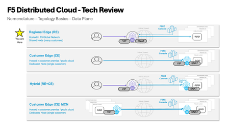
The guidelines presented in this walkthrough are informed by extensive field experience, incorporating insights from customers, F5 Solutions Engineers, Architects, and Professional Services teams. Having supported numerous deployments across diverse environments, this cumulative knowledge provides a practical and reliable starting point for publishing applications. This guide aims to help navigate the Distributed Cloud platform, offering a balanced approach to application delivery and security. The below figure represents the HTTP-LB configuration options alongside the typical flow of traffic from downstream client to upstream origin or application endpoint. Prerequisites: Article on how Distributed Cloud advertises and picks up traffic (Listener Logic) can be found here: F5 Distributed Cloud - Listener Logic Domains and Certificates: This is where you define what the load balancer listens on and how it presents itself to clients. For an initial deployment with a publicly accessible application, the following settings cover most use cases. We recommend a single HTTP-LB per application for visibility, telemetry, day 2 operations, and blast radius. Any more consolidation may cause friction going forward. Recommended Settings: Domain Name:Your application FQDN (e.g., app.example.com) Load Balancer Type: Certificate: Use F5 XC Auto-Cert when possible. If your domain is delegated to XC DNS, certificate management is fully automated. For non-delegated domains, F5 XC provides a cname challenge record value that you can add to your DNS provider to satisfy the Lets Encrypt ACME challenge, then add the provided Host Name.ves.io CNAME record pointing to XC to complete the certificate setup HTTP to HTTPS Redirect:Enable HSTS Header:Enable Listener Port: 443 Client-Side TLS: High security profile Protocol: HTTP/1.1 and HTTP/2 Origins and Health Checking: Origin Pools: A note on structure and origin access: Use Routes (covered in the next section) as the primary mechanism for attaching Origin Pools to your HTTP LB. The default Origin Pool field on the HTTP LB itself is best reserved as a potential fallback option depending on origin and route design (Engage your F5 SE if you need to discuss further). This approach gives you path-aware routing controls and per-route retry and timeout tuning. Also at the origin premise you should limit access to F5 Distributed Cloud RE’s only. You have a few options to achieve this. Limit via a security group or IP Access List to RE IP ranges, mTLS, insert a response header from the HTTP-LB that the origin server is expecting, or a combination of the 3. Recommended Settings for Publicly Available Endpoints: Origin Server Type: Public IP-based. Provide the IPv4 address directly. Where possible, target origins by IP with Host Header. If using public DNS-based origin endpoint targeting, be aware that XC does not honor standard DNS TTL and overrides the value! Origin Server Port: 443 Connection Pool Reuse: Enable Health Check Port: Endpoint port (same as origin port unless otherwise directed) Load Balancing Algorithm: Load Balancer Override (Load Balancer algorithm set at HTTP-LB) Endpoint Selection: Local Endpoints Preferred (Distributed Cloud Construct to leverage local endpoints over remote endpoints goal is to Egress the same RE as Ingress) TLS to Origin: Enable TLS SNI: Host Header TLS Security Level: High Origin Server Verification: Use Default Root CA Certificate mTLS: Disable unless required Other Origin Pool Options: Exception Handling: Setup for specific application/origin server requirements (configurable options available for application specific error-handling requirements) Origin Server Subsets: Disable unless you have a specific canary or subset routing requirement HTTP Protocol Configuration: Automatic (adjust to a specific version if your origin requires it) Proxy Protocol: Disable LB Source IP Persistence: Disable Health Checks: The default health check thresholds are tuned conservatively. In practice, this means a failed origin stays in rotation longer than it should, and a recovered origin comes back into rotation slowly. Adjust the thresholds to react more aggressively to recovery while still being tolerant of transient failures. Recommended Health Check Settings: Setting Recommended Value Default Why Healthy Threshold 1 3 Bring a recovered endpoint back into rotation after a single successful check Unhealthy Threshold 3 1 Require 3 consecutive failures before removing an endpoint — avoids flapping on transient issues Interval 15 seconds 15 seconds No change needed Jitter Percent 30% 30% Stagger health check timing across endpoints (30% of 15s = up to 4.5s offset) Key insight for jitter setting: When you have multiple endpoints in a pool, health checks without jitter all fire at the same instant that can create amongst other issues a temporary artificial network congestion or failure at endpoints. The 30% jitter setting randomizes the start time of each health check within a window (default: 15s interval with a 30% jitter, so checks are offset by up to 4.5 seconds). Leave this at the default unless you have a specific reason to change it. Advanced health check options: Host Header: Set to the value your application expects (do not leave blank if your origin validates the Host header) Path: Set a meaningful health endpoint like /healthz a common convention, but use whatever your application exposes Expected Status Codes: 200, 3xx Request/Response Header Manipulation: Add or remove headers as required by your application Expected http response: Validate the Raw Bytes expected in the Response of HTTP Health Check Origin Pool Display in UI: Routes: Routes are where your HTTP LB gains precision. Rather than sending all traffic to a single origin pool, Routes let you make forwarding decisions based on path, method, headers, and query parameters. They also expose per-route controls for timeouts, retries, header manipulation, and security policy controls that are not available at the origin pool level. Recommended Route Configuration: Route Type: Simple Route HTTP Method: Any Path Match: Prefix (use Regex or Exact match when you need more specificity) / Headers: Add header match conditions only if required Port Match: Adjust only if needed Origin targeting: Origin Pools:Add the Origin Pool(s) you configured in the previous section Host Rewrite Method: Automatic Host Rewrite (or set a specific value if your origin requires a fixed Host header) Query Parameters: Retain (Remove and Replace are available options) Route Activation: Enabled (Disable option) Advanced route options: Load Balancing Control: Use LB Hash Policy Priority: Default Origin Server Subsets: Leave unset unless subset routing is required Request/Response Manipulation: Header add/remove, cookie add/remove, set-cookie add/remove -configure as needed for your application Security (per-route overrides): WAF:Inherit from HTTP LB (recommended) or specify a different policy per route WAF Exclusion:Inherit from HTTP LB or specify an Exclusion Policy — see the note in the Gotchas section below on inline exclusions CORS and CSRF:Configure as needed Protocol Upgrades: SPDY:Disable (enable only if required) WebSockets:Disable (enable only if your application requires WebSocket support) Retry Policy: Key insight “retry values”: The retry settings below are tuned for typical HTTPS application traffic. The per-retry timeout of 1000ms prevents a slow origin from consuming the full route timeout on every attempt, and the retry interval backoff (25ms initial, 2500ms max) avoids hammering a struggling origin. Validate these values with load testing before going live. Custom Retry Policy Settings: Retry Conditions: 500 Gateway-error Connect-failure Refused-stream Reset Retriable-4xx Number of Retries: 3 Per-Retry Timeout: 1000ms Retry Interval: 25ms Max Retry Interval: 2500ms Miscellaneous Route Options: Route Timeout: 30000ms (30 seconds) Route-Specific Buffering: Common Mirroring: Disable Cluster Retract: Disable (validate with testing before enabling) Security Settings: Security configuration in F5 XC is layered. The settings below represent a solid baseline for an initial deployment. Individual applications will likely require tuning — use this as a starting point, not a final state. Web Application Firewall: The recommended starting posture is blocking mode with High and Medium attack signatures active. This catches the most common attack patterns while keeping false positive rates manageable. Do not start in detection-only mode and leave it there — establish a review cycle and move to blocking on a defined schedule. WAF: Enable Enforcement Mode: “Monitor” then after review migrate to “Blocking” Security Policy:Custom Attack Signatures: Default signature set High, Medium, and Low severity Automatic Attack Signature Tuning:Disable Automatic Signature Staging:Enable (7days) Threat Campaigns:Enable Violations:Default Signature-Based Bot Detection:Default Enhance with AI: Enable Mitigate High and Medium (have a review cadence) WAF Exclusion: Use a dedicated WAF Exclusion Policy object — do not use inline exclusions (see Gotchas below) Additional WAF-adjacent features — configure as needed for your application: Data Guard CSRF Protection GraphQL Inspection Cookie Protection API Protection: Enable as needed. If your application exposes a defined API surface, uploading an OpenAPI spec and enabling API Discovery is a worthwhile early step. Malware Protection: Disable DoS Settings: Mitigation Action: Block RPS Threshold: Typically based on Capacity of origin application endpoints Client-Side Challenge: Enabled if web based application Custom Service Policy for DoS: Apply a specific geo location and IPI during DDoS DDoS Mitigation Rules: Default Slow DDoS: Default Service Policies: Service Policies match on a set of criteria and apply an action. They operate at the connection level and complement WAF, which operates at the request content level. Service Policies: Apply Specified Service Policies (list any access restriction policies you need) IP Reputation: select the reputation categories appropriate for your threat model Threat Mesh: Disable User Identifier Policy: Create a policy using Client IP and TLS Fingerprint based on JA4 as identifiers (other identifier types are available) Malicious User Detection: Enable Malicious User Mitigation: Enable, Default settings Rate Limiting: Configure as needed based on expected traffic profile Trusted Client Rules: Configure as needed Client Blocking Rules: Configure as needed CORS Policy: Configure as needed Other Settings: VIP Advertisement: This is what makes the HTTP LB publicly reachable through the F5 Regional Edge network. If you change this to a Custom setting, validate your advertisement policy carefully as a misconfiguration here means no traffic reaches your LB. Advertise Internet Load Balancing Algorithm: Choose based on your application's session and traffic characteristics. Round Robin is the default and works for most stateless applications. If you have session affinity requirements, evaluate the hash-based options. Trusted Client IP: Disable unless you have a specific use case that requires preserving the original client IP through a proxy chain upstream of XC. Location Header: Enable “Add XC RE Ingress Location” to include the Regional Edge location in response headers. This is useful for troubleshooting and for understanding which RE node handled a request. Header and Cookie Options: Configure request/response header additions, removals, and cookie manipulation as required by your application. Error Response: Configure custom error response pages as needed. The default F5 error pages are functional but not branded. Most production deployments will want custom responses for 4xx and 5xx errors. Buffer Policy: Default: No buffering (requests are streamed to the origin) Max Buffer Size: 10,485,760 bytes (10MB) – if the request body exceeds this, XC returns HTTP 413 (Payload Too Large) Timeout behavior: If the full request body is not received before the timeout, XC returns HTTP 408 (Request Timeout) When to enable: Enable buffering if your origin cannot handle streaming request bodies, or if you are using WAF inspection on large POST requests Compression: Algorithm: GZIP only (not configurable) Compression Level: 5 (not configurable) Behavior: XC compresses responses dispatched from the upstream origin when the client signals support via “Accept-Encoding” Enable if your origins do not already compress responses and your client traffic includes browser-based users Idle Timeout: Default: Client Side - 30 seconds Behavior: A stream with no activity (upstream or downstream) for this duration is terminated with HTTP 504 Increase for applications with long-running server-sent events, streaming responses, or slow upload scenarios Common Gotchas: These are the issues that come up repeatedly in initial deployments. Check these before you go live. Using DNS-based origin targeting instead of IP + Host Header: By default Distributed Cloud rewrites the host header so validate and set appropriately. DNS-based origin targeting works but introduces a dependency on DNS TTL behavior that XC does override in non-standard ways. During a failover event, you may experience stale resolution longer than you expect. Use IP-based origin with Host Header wherever possible for predictable behavior. Not Configuring a Health Check at all or Leaving health check thresholds at defaults: By default, a health check is not added to an origin pool. Also, the default Healthy Threshold of 3 means a recovered origin must pass 3 consecutive checks before re-entering rotation. If your check interval is 15 seconds, that is 45 seconds of unnecessary exclusion for an endpoint that came back healthy. Set Healthy Threshold to 1. The default Unhealthy Threshold of 1 is the opposite problem a single failed check removes the endpoint. Set Unhealthy Threshold to 3 to tolerate transient blips. Attaching Origin Pools directly to the HTTP LB instead of utilizing Routes: The default Origin Pool field on the HTTP LB is a catch-all fallback. If you attach your primary origin there and do not configure Routes, you lose access to per-route retry policies, timeouts, header manipulation, and security overrides. Build your routing structure with explicit Routes from the start. Starting in WAF Monitor mode and never switching to blocking: Monitoring mode is a valid tuning step, but it is easy to leave it there indefinitely. Set a review date when you configure monitor mode. Establish your false positive baseline and move to blocking on a defined timeline. Not setting a Host Header on the health check: Leaving the Idle Timeout at 30 seconds for streaming applications: The 30-second idle timeout will terminate long-lived connections, WebSocket connections, server-sent event streams, slow uploads without warning. If your application uses any of these patterns, increase the Idle Timeout before testing.107Views1like0CommentsMalware Protection with F5 Distributed Cloud Web App & API Protection
F5 Distributed Cloud WAAP comes with robust malware protection built with the precision and scope to address the unique challenges of safeguarding file uploads. Allowing users to upload files is a staple of web applications. Whether it's uploading images for insurance claims, profile photos for social networks, or text files like tax documents, file uploads play an essential role in modern digital workflows. However, this convenience comes with a hidden and significant risk: file upload endpoints can be a vector for injecting and executing malicious code. While traditional web application firewalls (WAFs) often excel at detecting code injection attacks in textual request bodies or URL parameters, they falter when it comes to binary files. Binary files represent a unique challenge—malware can be embedded in hard-to-detect formats like images, PDFs, or other file types, making traditional WAF signatures and detection models unable to detect such attacks. Compounding the problem, many organizations face significant hurdles when using WAFs to monitor file uploads. To prevent excessive false positives that disrupt legitimate user activity, development and security teams often opt to bypass WAF protection for file uploads or define overly broad exclusions for upload paths. These exclusions create blind spots in application defenses, effectively leaving upload endpoints and, by extension, the wider application ecosystem vulnerable to exploitation. F5 Distributed Cloud WAAP is available with robust malware protection that has been built with the precision and scope to address the unique challenges of safeguarding file uploads. In this demo we will show you how to enable Malware Protection on your F5 Distributed Cloud Load Balancer to detect and block malicious file uploads. For more info on configuring Malware Protection on your F5 Distributed Cloud Load Balancer, see Create HTTP Load Balancer > Configure Malware Protection.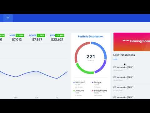 130Views2likes0Comments