Infrastructure as Code: Automating F5 Distributed Cloud CEs with Ansible
Introduction Welcome to the first installment of our Infrastructure as Code (IaC) series, focusing on F5 products and Ansible. This series has been a long-standing desire of mine to showcase the ability of IaC utilizing Ansible Automation Platform to deliver Day 0 through Day 2 operations with multiple F5 virtualized platforms. Over time, I've encountered numerous financial clients expressing interest in this topic. For many of these clients, the prospect of leveraging IaC to redeploy an environment outweighs the traditional approach of performing upgrades. This series will hopefully provide insight, documentation, and code for anyone embarking on this journey. Why Ansible Automation Platform? Like most people, I started my journey with community editions of Ansible. As my coding became more complex, so did the need to ensure that my lab infrastructure adhered to the best security guidelines required by my company (my goal being to mimic how customers would/should do things in real life). I began utilizing Ansible Automation Platform to ensure my credentials were protected, as well as to organize and share my code with the rest of my team (following the 'just in case you got hit by a bus' theory). Ansible Automation Platform utilizes execution environments (EE) to ensure code runs efficiently and cleanly every time. Now, I am also creating Execution Environments via GitHub with workflows and pushing them up to Quay.io (https://github.com/VDI-Tech-Guy/f5-execution-engines). Huge thanks to Colin McNaughton at Red Hat for making my life so much easier with building EEs! Why deploy F5 Distributed Cloud on VMware vSphere? As I mentioned before, I had this desire to build this Infrastructure as Code (IaC) code a while back. This was prior to the Broadcom acquisition of VMware. Being an ex-VMware employee, I had a lot of knowledge of virtualization platform infrastructure going into this project, and I started my focus on deploying on VMware vSphere. F5 Distributed Cloud can be deployed in any cloud, anywhere. However, I really wanted to focus on on-premises deployments because not every customer can afford the cloud. Moreover, there's always a back-and-forth battle between on-premises and the cloud, which has evolved into the Hybrid Cloud and the Multi-Cloud. I do intend to extend this series to the Multi-Cloud, but these initial deployments will be focused on VMware vSphere, as it is still utilized in many organizations across the globe. Information about the Setup in the Demo Video If you watch the video (down below) on how the deployment works, you can see i did a bunch of the pre-work prior to launching the deployment, in the git repostory (link in Resources). Here are some Prework items i did Had a fully functional Ansible Automation Platform 2.4+ enviornment setup and working. (at the time the controller version was 4.4.4) Execution Environment was imported into Ansible Automation Platform Controller The Project was setup to import the Playbooks from the Git Repository (In Resources Section below) and setup the Default Execution Environment Demo Inventory was setup (in our usecase we only needed the vCenter Host) We Setup Network Credentials for the vCenter The Template was setup and had Variables populated in it (Note the API Key was hidden). As mentioned in the Video (Below) The variables were populated to my environment, this contains all the information, i have provided a Demo Example in the git repository for anyone to mimic my settings to their environment, also the example has comments about each field or area of a field and the purpose of the variable. { "rhel_location": "https://vesio.blob.core.windows.net/releases/rhel/9/x86_64/images/vmware/rhel-9.2023.29-20231212012955-single-nic.ova", "xc_api_credential": "_____________________________________", "xc_namespace": "mmabis-automation", "xc_console_host": "f5-bd", "xc_user": "admin", "xc_pass": "Ansible123!", "vcenter_hostname": "{{ ansible_host }}", "vcenter_username": "{{ ansible_env.ANSIBLE_NET_USERNAME }}", "vcenter_password": "{{ ansible_env.ANSIBLE_NET_PASSWORD }}", "vcenter_validate_certs": false, "datacenter_name": "Apex", "cluster_name": "Worlds-Edge", "datastore": "TrueNAS-SSD", "dvs_switch_name": "DSC-DVS", "dns_name_servers": [ "192.168.192.20", "192.168.192.1" ], "dns_name_search": [ "dsc-services.local", "localdomain" ], "ntp_servers": [ "0.pool.ntp.org", "1.pool.ntp.org", "2.pool.ntp.org" ], "domain_fqdn": "dsc-services.local", "DVS_Name": "{{dvs_switch_name}}", "Internal_Network": "DVS-Server-vLan", "External_Network": "DVS-DMZ-vLan", "resource_pool_name": "Lab-XC", "waiting_period": 2, "temp_download_location": "/tmp/xc-ova-download.ova", "xc_ova_builds": [ { "hostname": "xc-automation-rhel-demo", "tmpl_name": "xc-automation-rhel-demo", "admin_password": "Ansible123!", "cluster_name": "xc-automation-cluster-rhel-demo", "dhcp": "no", "external_ip": "172.16.192.170", "external_ip_subnet_prefix": "24", "external_ip_gw": "172.16.192.1", "external_ip_route": "0.0.0.0/0", "internal_ip": "192.168.192.170", "internal_ip_subnet_prefix": "22", "internal_ip_gw": "192.168.192.1", "certified_hw": "vmware-regular-nic-voltmesh", "latitude": "39.51833126", "longitude": "-104.759496962", "build_count": 3, "nic_config": "rhel-multi" } ] } Launching the Code With all of that prework Handled it was as easy as launch the code, there were a few caviats i learned over time when dealing with the atuomation that i wanted to share. Never re-use a cluster name in F5 Distributed Cloud, especially if it was used in a different version of the CE (there were communications issues with the CEs and previous cluster information that was stored in F5 Distributred Cloud Console) The Api Credentials are system level when trying to accept registration or create the token for importing in to the environment. This code is designed to check for "{{ xc-namespace}}-token" if it exists then it will utilize the existing token, if not it will try to create it so you need system level permissions to do this. Build Count should be 3 by default (still needs to be defined) or an ODD number based on recomendations i have heard from our F5 Field. If there are more that i think of ill definatly edit the post and make sure its up-to-date. When launching the code i was able to get the lab to build up correctly multiple times, so please if there is an issue or something i might not have documented well, feel free to let me know and give it a shot for yourself! YouTube Video now on DevCentral Channel Resources https://github.com/f5devcentral/f5-bd-ansible-day0-automation - The Code utilized for this deployment https://github.com/VDI-Tech-Guy/f5-execution-engines - Building Execution Environments with Github and Workflows Conclusion I do hope that this series will help everyone who wants to embrace IaC and if you have any questions feel free to reach out!301Views3likes0CommentsHorizon Blast Extreme UDP with BEAT Support Functionality in BIG-IP Access Manager 14.0!
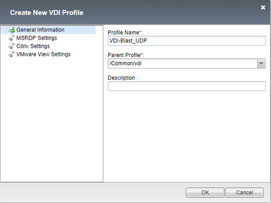
Hey All, Just wanted to provide an update on new features that were added to BIG-IP Access Manager (Formerly APM) 14.0 for VMware Horizon. Listed below are the new features that were added into Access Manager for VMware Workspace ONE and VMware Horizon. APM supports Blast Extreme protocol over TCP and UDP and also supports the Blast Extreme Adaptive Transport (BEAT) for Desktops and Applications. APM supports access to VMware Horizon desktops and applications using VMware Workspace ONE as an IDP for more information on this check out the integration guide at https://f5.com/Portals/1/PDF/Partners/apm-proxy-with-workspace-one-integration-guide.pdf What is the VMware Horizon Blast Extreme TCP/UDP with BEAT Feature? Since the release of Blast Extreme in Horizon 7, F5 has supported the TCP functionality of the Blast code allowing for the VMware Horizon native client and HTML5 client's to connect to desktops and apps. BIG-IP (14.0) now supports the UDP and BEAT functionality of the Blast Extreme code. What is BEAT? BEAT or Blast Extreme Adaptive Transport allows the switching between TCP and UDP of the Blast Extreme Transport based on the connected clients conditions. For example, when a client is connected over a mobile network sometimes the connectivity is unstable (packet loss and/or high latency), with a typical TCP connection packet loss will retransmit the packet over and over again creating lag from a user's desktop or app perspective in Horizon. BEAT was designed to adapt to these types of connections and will detect those packets being lost and adjust the protocol from the connected client from TCP to UDP to allow the dropped packets to be lost and continue moving forward allowing the user to have a more seamless desktop experience. BEAT also has the ability to switch from UDP to TCP depending on the clients connectivity. Is there an iAPP to Enable Blast UDP? Currently there is not an iAPP for this functionality and the existing iAPP will only create the TCP functionality for the Blast Extreme Protocol. F5 intends to release a build soon to resolve this issue, this article is being posted to help customers manually create the Virtual Server to allow for the Blast Extreme Functionality prior to the iAPP fix. Here is the information needed to implement the Blast UDP functionality which will enable BEAT. NOTE: This will need to be removed when the iAPP is upgraded later to allow for the feature/function Create a VDI Profile Creating the VDI Profile for Blast Extreme Navigate to Access --> Connectivity/VPN --> VDI/RDP --> VDI Profiles. Create a new profile Name it whatever you want Change Parent Profile to “/Common/vdi” In VMware View Settings change from PCoIP to Blast Extreme Create a Virtual IP for the Blast Extreme UDP Port Provide a Unique Name Match the Destination Address with existing Horizon APM Deployment Service Port: 8443 Source Address Translation: Automap VDI Profile: Select previously created VDI Profile Click Finished to Create the VIP Validation/Testing Once completed you can test the connection, I recommend using the VMware Horizon Performance Tracker as you can see the BEAT protocol in action changing from TCP to UDP.3.8KViews2likes3CommentsVMware Cloud for AWS - BIG-IP in Single-Site, Hybrid, and Multi-Cloud Deployments
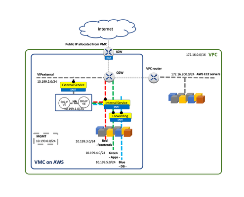
Introduction This is article 2 of 2. The aim is to provide useful information for planning a VMC/multi-cloud deployment, for example when creating an HLD (High Level Design) document. For information about VMC and relevant aspects for BIG-IP please see the previous article VMware Cloud for AWS - Networking and High Availability. VMC uses NSX-T for networking but currently AWS only allows a single Tier-1 Gateway hence limiting the networking topologies possible. In this blog post we describe a suggested topology for BIG-IP in VMC for AWS. This baseline arrangement can be used in the multi-cloud sample topology exposed. A mention to VMware’s HCX migration tool is also done. BIG-IP in a single site Out of the 4 topologies described In the F5 BIG-IP deployment guide for NSX-T the customers are currently constrained to Topology D which uses SNAT by default. This topology is shown in the next diagram. In this sample topology, we create a typical 3-tier architecture with Frontend (External Service), Application (Internal Service) and Database tiers. Notice that the Database Tier is configured as “Disconnected” to provide an additional layer of secure by means of controlling the access through a VIP in the BIG-IP. The above topology can be expanded with multiple BIG-IP Scale-N clusters. This would allow isolation between the different Business Units or departments, each one with their own BIG-IP Scale-N cluster. Out of scope of this blog but worth to remind is that in these multi-cluster BIG-IP deployments (in a single or multiple sites) BIG-IQ can be used for global visibility across sites and centralized management. Using EC2 workloads From the point of view of the BIP-IPs, VMC is just another routing environment where it can also access EC2 workloads. These workloads can be dynamically incorporated in BIG-IP’s configuration by means of using AS3’s Service Discovery feature. Moreover, reachability of the VMs is the same either from VMC to VPC or vice versa. The same applies to the Internet access. This opens the following dilemmas: Where to place the BIG-IPs? Where to place the Internet Gateway? There is no definitive answer. We can choose whether we want each functionality in the AWS VPC or in the VMC side. This is shown in the next figure. The decision should consider the following aspects: At time of this writing, using an AWS IGW instead of an IGW via VMC has the possibility of using ELBs which provides Advanced Shield capabilities. The cost will depend where we have more traffic and where we have more compute resources. Using HCX VMware's HCX covers several migration-related use cases including Disaster Recovery. HCX's Network Extension capability permits keeping the same IP and MAC addresses during a VM migration. This minimizes service disruption and is transparent to all devices including BIG-IP. Furthermore, HCX doesn’t mandate how the services are exposed externally therefore GSLB is always a valid option and will provide greater flexibility compared to a plain routing option. BIG-IP in Multi-cloud Multi-cloud allows for many use cases, as a consequence, many designs are possible. Ultimately the design will be highly dependent on the applications and on the databases, which most of the times require replication across sites. From the point of BIG-IP there are very few restrictions. Next we will describe two multi-cloud scenarios: A hybrid design focused in local data retention implemented with a single site plus cloud bursting. A generic multi-cloud design that can be applied to any public cloud or private data centers. Single site with cloud bursting design The topology to be described next is suitable for smaller deployments or when data must be stored on-premises, usually because of data retention policies or regulations. This can be observed in the next figure where the DB Tier is not stretched to the Public Cloud. In this architecture the On-premises data center is stretched to a public cloud when load conditions require increasing the compute needs. In this scenario Internet access is kept in the On-premises data center. It requires the use of a high performance Direct Connect link with low latency. This is usually within the metropolitan area of the On-premises facility. This Direct Connect circuit needs to be established once and its capacity increased ahead of the peak periods. Some housing vendors allow to change circuit’s capacity programmatically. When compute changes dynamically, it is a perfect fit for F5’s Service Discovery feature of AS3, automatically populating the pools with the added or removed computing instances. Please check the clouddocs.f5.com site for this and other automation options. Generic multi-Cloud design In general, F5 recommends Global Server Load Balancing (GSLB) for multi-cloud because it has the following benefits: cross-cloud vendor, name based/high degree of control, stickiness and IP intelligence.GSLB is available by F5 in two form factors: Software as a Service (SaaS) with F5 Cloud Services’ DNS LB service and Self-managed with F5 BIG-IP’s DNS module. Designs depend on the applications and on databases. Inter-site dependencies play a crucial role. This guide recommends following the next design principles to minimize cost and maximize reliability while keeping simplicity in mind: Typically, ADCs like BIG-IP deal with Frontend-tier and App-tier servers which should not have to talk with peers in other sites. These tiers have the most throughput and latency demands so inter-site communication should be avoided. Otherwise, this could incur in uneven performance and increased and unnecessary costs. Identify strictly necessary inter-site dependencies. The typical case is DB replication which has much less throughput demands. Also, latency is a lesser issue because replication often happens asynchronously. There are other very relevant sources of inter-site traffic such as Automation, VM migration and data-store replication (for example a repository of images). VMware’s HCX traffic fits in this category. The first two items in this list deal with traffic that is generated upon client requests (blue arrows in the figure below). On the other hand, the third item is a new category of traffic (orange arrows) that is not expected to have dependencies when handling an ongoing customer request. Another characteristic of this traffic is that its traffic demands will greatly depend on frequency of updates in the applications. Simpler sites are easier to manage, scale, and replicate. GSLB allows for distribution of workloads based on a site’s or a service’s load and capacity so it is perfectly fine to have differently sized data centers. The most important attribute is to have them architecturally equal. Automations that are cross-cloud vendor capable are advised. Using BIG-IP DNS and following the above guidelines we can create a cross-cloud vendor solution using GSLB. This is shown in the next figure. Probably the most remarkable aspect of the diagram are the network dependencies and demands which drive the design. In this diagram Inter-site dependency is reduced to the minimum, typically DB replication only. We can also see that there is additional inter-site traffic like the BIG-IP DNS iQuery (used for service discovery and health probing) but this traffic is different in nature because it is failure tolerant. In the design above, the DNS functionality is implemented in a standalone BIG-IPs because redundancy is accomplished by having an independent BIG-IP DNS at each site. Having this BIG-IP DNS separated from the BIG-IP Scale-N cluster that handles client traffic gives clarity in the diagram and more relevantly sets a clear demarcation of functions. If desired, the BIG-IP DNS functionality can be consolidated in the BIG-IP Scale-N cluster at each site. At extract cost, BIG-IP DNS could be placed in Internet exchanges. This allows: To be closer to the clients. This only slightly improves DNS performance since client’s local DNS resolvers usually reply from their DNS cache. To have a closer view to client’s network performance and reachability to the clouds. This is very relevant. At the end of the day all designs have their PROs and CONs and a balancing act has to be done. In any case simplicity should always be priority. With respect to this, BIG-IP DNS has very little constains and greatly simplifies any existing deployment by having automatic service discovery Conclusion BIG-IP integrates in VMC likewise in NSX-T by using routing. In the case of VMC on AWS at present there are limitations which inhibit using the same topologies than on the private clouds. BIG-IQ can be leveraged to simplify the management of multiple BIG-IPs in the same or multiple sites. GSLB is king for multi-cloud deployments. It is cross cloud vendor and provides greater flexibility and functionality over plain routed options. Multi-cloud is a wide topic and we refer to the F5 BIG-IP deployment guide for NSX-T for more detailed discussion on the topics described in this blog.984Views1like1CommentVMware Cloud for AWS - Networking and High Availability
Introduction This is the first article in a series of two articles which aim to be useful when planning a VMware Cloud/multi-cloud deployment, for example when creating an HLD (High Level Design) document. This first article is about the relevant aspects of VMware Cloud for BIG-IP. The second article, VMware Cloud for AWS - BIG-IP in Single-Site, Hybrid, and Multi-Cloud Deployments, will cover several designs. VMware Cloud Overview Many public cloud providers offer VMware Cloud (aka VMC), all are based on the same set of technologies mainly vSphere, NSX-T networking and vSAN storage. It is important to check the requisites because not all providers provide the same features or are developed to the same level. At time of this writing AWS is VMware’s preferred public cloud provider. VMC on AWS is a managed service provided and billed by VMware. It has the additional features of having access to EC2 workloads, AWS services and flexible access to on-premises deployments (private clouds). VMware Cloud on AWS, networking and high availability A VMC on AWS deployment has its own VPC. From operations point of view, management is done through a vCenter and NSX-T management is performed with a constrained NSX manager web UI. This VPC can be seen from AWS’s console. For production environments VMC on AWS deployments should be configured as “stretched cluster” in which case the VMware components and customer workloads are in two AWS Availability Zones. BIG-IPs should be distributed among these Availability Zones. Thanks to NSX-T’s overlays, the segments spawn transparently across these two Availability Zones, greatly simplifying networking. From vCenter point of view each Availability zone is seen as a Fault Domain as it can be seen in the next picture. When deploying a VM you can choose an ESXi host in the desired Fault Domain/AWS AZ. In case of failure, the VM will stay in its original Fault Domain/AWS AZ if possible. Likewise all VMC implementations, VMC on AWS uses NSX-T for networking. VMC for AWS uses a prescriptive model with the following characteristics: Customer doesn’t have access to the Tier-0 Gateway. Only one Tier-1 Gateway is possible. This is called the Compute Gateway in VMC for AWS. Overlapping addresses within the VMC’s VPC are not possible. The Service Insertion feature is not available. No bundled Load Balancer: the native NSX-T LB is not available. These limits the possible topologies out of the 4 sample topologies described in the F5 BIG-IP deployment guide for NSX-T, customers are currently constrained to Topology D which uses SNAT by default. A detailed view of VMC on AWS networking can be seen in the next diagram. Given that at present VMC on AWS provides a single Tier-1 Gateway If a customer wanted to have a replica of an existing private cloud design it would require a separate SDDC per existing Tier-1 Gateway in the private cloud with the corresponding increase of cost. A redesign collapsing several Tier-1 Gateways of the private cloud into one Tier-1 Gateway in VMC on AWS will be needed. Conclusion VMC on AWS is an enabler on the multi-cloud journey by minimizing the need to adapt existing know-how and existing automations used in the private clouds. Being a managed solution makes it even easier for going to the public clouds. At present VMC on AWS greatly limits the possible topologies compared to a private cloud of VMware with NSX-T. This is mainly because of only allowing a single Tier-1 Gateway per SDDC. Once this limitation is removed designs used in private and VMC on AWS clouds will be more homogeneous.946Views1like0CommentsSecuring your VMware Remote Solutions to Support COVID-19 Work From Home Scaling
Many of us are now working from home in unprecedented numbers. For infrastructure teams it's putting impressive strain on remote work solution. Building off our primary DevCentral COVID-19 article, our support teams and solution architects are hearing from many of you asking us for new and better ways to expand VMware capabilities with F5 BIG-IP Local Traffic Manager (LTM) and Access Policy Manager (APM). Get started securing your VMware remote working solutions with the field-recommended guides below. F5 with VMware Virtual Desktop Infrastructure (VDI) Solutions (Horizon View, Workspace ONE) How to deploy F5 with Horizon View using iApps This is a comprehensive guide for deploying F5 BIG-IP APM with VMware Horizon. Walk through the F5 iApp to assist in configuring APM with VMware Horizon View. How to use BIG-IP LTM in front of VMware Horizon Unified Access Gateway This guide will show step by step guidance on how to use F5 BIG-IP LTM to increase the scale and resiliency of either greenfield or brownfield VMware Horizon deployments. How to Deploy F5 APM with VMware ONE Providing a step-by-step instruction for setting up F5 BIG-IP APM as a proxy gateway for VMware Horizon with VMware Workspace ONE. How to deploy F5 BIG-IP LTM with VMware Workspace ONE Identity Manager (vIDM) This guide provides step-by-step instructions for setting up the first Identity Manager virtual appliance (Node 1), for production implementations. VMware recommends the deployment of two (2) additional nodes for three (3) total. Nodes 2 and 3 will be cloned from the first node after it's been configured and setup with the F5 BIG-IP to provide a fully load-balanced configuration. Reach Out To Us As our technical teams work with our users to provide continuous COVID-19 coverage, you may still need additional information we haven't surfaced yet. If you can't determine what best meets your requirements, let us know in the comments or reach out to our technical community. Don't forget to check out AskF5, our support knowledge center.1.1KViews1like0Comments