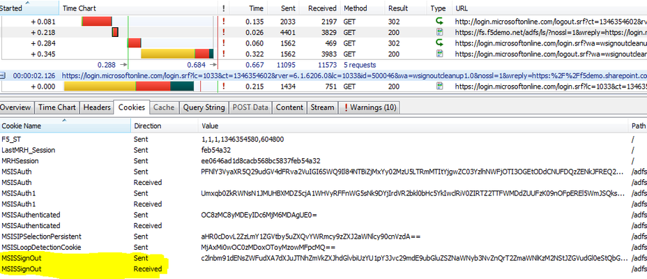
Bidirectional Forwarding Detection (BFD) Protocol Cheat Sheet
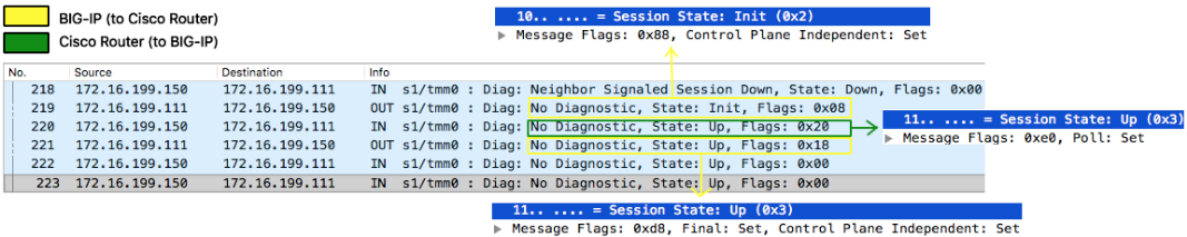
Definition This is a protocol initially described inRFC5880and IPv4/IPv6 specifics inRFC5881. I would say this is an aggressive 'hello-like' protocol with shorter timers but very lightweight on the wire and requiring very little processing as it is designed to be implemented in forwarding plane (although RFC does not forbid it to be implemented in control plane). It also contains a feature called Echo that further leaves cpu processing cycle to roughly ZERO which literally just 'loops' BFD control packets sent from peer back to them without even 'touching' (processing) it. BFD helps routing protocol detects peers failure at sub-second level and BIG-IP supports it on all its routing protocols. On BIG-IP it is control-plane independent as TMM that takes care of BFD sending/receivingunicastprobes (yes,no multicast!) and BIG-IP's Advanced Routing Module® being responsible only for its configuration (of course!) and to receive state information from TMM that is displayed in show commands. BIG-IP's control plane daemon communicates with TMM isoamd. This daemon starts when BFD is enabled in the route domain like any other routing protocol. BFD Handshake Explained 218: BFD was configured on Cisco Router but not on BIG-IP so neighbour signals BIG-IP sessionstate is Down and no flags 219: I had just enabled BFD on BIG-IP, session state is now Init and only Control Plane Independent flag set¹ 220: Poll flag is set to validate initial bidirectional connectivity (expecting Final flag set in response) 221: BIG-IP sets Final flag and handshake is complete² ¹Control Plane Independentflag is set because BFD is not actively performed by BIG-IP's control plane. BIG-IP's BFD control plane daemon (oamd) just signals TMM what BFD sessions are required and TMM takes care of sending/receiving of all BFD control traffic and informs session state back to Advanced Routing Module's daemon. ²Packets 222-223are just to show that after handshake is finished all flags are cleared unless there is another event that triggers them. Packet 218 is how Cisco Router sees BIG-IP when BFD is not enabled. Control Plane Independent flag on BIG-IP remains though for the reasons already explained above. Protocol fields Diagnostic codes 0 (No Diagnostic): Typically seen when BFD session is UP and there are no errors. 1 (Control Detection Time Expired):BFD Detect Timer expired and session was marked down. 2 (Echo Function Failed):BFD Echo packet loop verification failed, session is marked down and this is the diagnostic code number. 3 (Neighbor Signaled Session Down):If either neighbour advertised state or our local state is down you will see this diagnostic code 4 (Forwarding Planet Reset):When forwarding-plane (TMM) is reset and peer should not rely on BFD so session is marked down. 5 (Path Down):Ondemand mode external application can signal BFD that path is down so we can set session down using this code 6 Concatenated Path Down): 7 (Administratively Down):Session is marked down by an administrator 8 (Reverse Concatenated Path Down): 9-31:Reserved for future use BFD verification 'show' commands ³Type IP address to see specific session Modes Asynchronous(default): hello-like mode where BIG-IP periodically sends (and receives) BFD control packets and if control detection timer expires, session is marked as down.It uses UDP port3784. Demand: BFD handshake is completed but no periodic BFD control packets are exchanged as this mode assumes system has its own way of verifying connectivity with peer and may trigger BFD verification on demand, i.e. when it needs to use it according to its implementation.BIG-IP currently does not support this mode. Asynchronous + Echo Function: When enabled, TMM literally loops BFDecho-specificcontrol packetson UDP port 3785sent from peers back to them without processing it as it wasn't enough that this protocol is already lightweight. In this mode, a less aggressive timer (> 1 second) should be used for regularBFD control packets over port 3784 and more aggressive timer is used by echo function.BIG-IP currently does not support this mode. Header Fields Protocol Version:BFD version used. Latest one is v1 (RFC5880) Diagnostic Code: BFD error code for diagnostics purpose. Session State: How transmitting system sees the session state which can be AdminDown, Down, Init or Up. Message Flags:Additional session configuration or functionality (e.g. flag that says authentication is enabled) Detect Time Multiplier:Informs remote peer BFD session is supposed to be marked down ifDesired Min TX Intervalmultiplied by this value is reached Message Length(bytes):Length of BFD Control packet My Discriminator:For each BFD session each peer will use a unique discriminator to differentiate multiple session. Your Discriminator:When BIG-IP receives BFD control message back from its peer we add peer's My Discriminator to Your Discriminator in our header. Desired Min TX Interval(microseconds):Fastest we can send BFD control packets to remote peer (no less than configured value here) Required Min RX Interval(microseconds):Fastest we can receive BFD control packets from remote peer (no less than configured value here) Required Min Echo Interval(microseconds):Fastest we can loop BFD echo packets back to remote system (0 means Echo function is disabled) Session State AdminDown:Administratively forced down by command Down: Either control detection time expired in an already established BFD session or it never came up.If probing time (min_tx) is set to 100ms for example, and multiplier is 3 then no response after 300ms makes system go down. Init:Signals a desire to bring session up in the beginning of BFD handshake. Up:Indicates session is Up Message Flags Poll:Pool flag is just a 'ping' that requires peer box to respond with Final flag. In BFD handshake as well as in Demand mode pool message is a request to validate bidirectional connectivity. Final:Sent in response to packet with Poll bit set Control Plane Independent:Set if BFD can continue to function if control plane is disrupted¹ Authentication Present:Only set if authentication is being used Demand:If set, it is implied that periodic BFD control packets are no longer sent and another mechanism (on demand) is used instead. Multipoint:Reserved for future use of point-to-multipoint extension. Should be 0 on both sides. ¹ This is the case for BIG-IP as BFD is implemented in forwarding plane (TMM) BFD Configuration Configure desired transmit and receive intervals as well as multiplier on BIG-IP. And Cisco Router: You will typically configure the above regardless of routing protocol used. BFD BGP Configuration And Cisco Router: BFD OSPFv2/v3 Configuration BFD ISIS Configuration BFD RIPv1/v2 Configuration BFD Static Configuration All interfaces no matter what: Specific interface only: Tie BFD configuration to static route:8.8KViews0likes7CommentsBig-IP and ADFS Part 1 – “Load balancing the ADFS Farm”
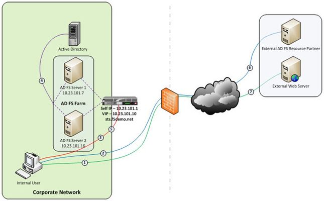
Just like the early settlers who migrated en masse across the country by wagon train along the Oregon Trail, enterprises are migrating up into the cloud. Well okay, maybe not exactly like the early settlers. But, although there may not be a mass migration to the cloud, it is true that more and more enterprises are moving to cloud-based services like Office 365. So how do you provide seamless, or at least relatively seamless, access to resources outside of the enterprise? Well, one answer is federation and if you are a Microsoft shop then the current solution is ADFS, (Active Directory Federation Services). The ADFS server role is a security token service that extends the single sign-on, (SSO) experience for directory-authenticated clients to resources outside of the organization’s boundaries. As cloud-based application access and federation in general becomes more prevalent, the role of ADFS has become equally important. Below, is a typical deployment scenario of the ADFS Server farm and the ADFS Proxy server farm, (recommended for external access to the internally hosted ADFS farm). Warning…. If the ADFS server farm is unavailable then access to federated resources will be limited if not completely inaccessible. To ensure high-availability, performance, and scalability the F5 Big-IP with LTM, (Local Traffic Manager), can be deployed to load balance the ADFS and ADFS Proxy server farms. Yes! When it comes to a load balancing and application delivery, F5’s Big-IP is an excellent choice. Just had to get that out there. So let’s get technical! Part one of this blog series addresses deploying and configuring the Big-IP’s LTM module for load balancing the ADFS Server farm and Proxy server farm. In part two I’m going to show how we can greatly simplify and improve this deployment by utilizing Big-IP’s APM, (Access Policy Manager) so stay tuned. Load Balancing the Internal ADFS Server Farm Assumptions and Product Deployment Documentation - This deployment scenario assumes an ADFS server farm has been installed and configured per the deployment guide including appropriate trust relationships with relevant claims providers and relying parties. In addition, the reader is assumed to have general administrative knowledge of the BIG-IP LTM module. If you want more information or guidance please check out F5’s support site, ASKF5. The following diagram shows a typical, (albeit simplified) process flow of the Big-IP load balanced ADFS farm. Client attempts to access the ADFS-enabled external resource; Client is redirected to the resource’s applicable federation service; Client is redirected to its organization’s internal federation service, (assuming the resource’s federation service is configured as trusted partner); The ADFS server authenticates the client to active directory; The ADFS server provides the client with an authorization cookie containing the signed security token and set of claims for the resource partner; The client connects to the resource partner federation service where the token and claims are verified. If appropriate, the resource partner provides the client with a new security token; and The client presents the new authorization cookie with included security token to the resource for access. VIRTUAL SERVER AND MEMBER POOL – A virtual server, (aka VIP) is configured to listen on port 443, (https). In the event that the Big-IP will be used for SSL bridging, (decryption and re-encryption), the public facing SSL certificate and associated private key must be installed on the BIG-IP and associated client SSL profile created. However, as will be discussed later SSL bridging is not the preferred method for this type of deployment. Rather, SSL tunneling, (pass-thru) will be utilized. ADFS requires Transport Layer Security and Secure Sockets Layer (TLS/SSL). Therefore pool members are configured to listen on port 443, (https). LOAD BALANCING METHOD – The ‘Least Connections (member)’ method is utilized. POOL MONITOR – To ensure the AD FS service is responding as well as the web site itself, a customized monitor can be used. The monitor ensures the AD FS federation service is responding. Additionally, the monitor utilizes increased interval and timeout settings. The custom https monitor requires domain credentials to validate the service status. A standard https monitor can be utilized as an alternative. PERSISTENCE – In this AD FS scenario, clients establish a single TCP connection with the AD FS server to request and receive a security token. Therefore, specifying a persistence profile is not necessary. SSL TUNNELING, (preferred method) – When SSL tunneling is utilized, encrypted traffic flows from the client directly to the endpoint farm member. Additionally, SSL profiles are not used nor are SSL certificates required to be installed on the Big-IP. In this instance Big-IP profiles requiring packet analysis and/or modification, (ex. compression, web acceleration) will not be relevant. To further boost the performance, a Fast L4 virtual server will be used. Load Balancing the ADFS Proxy Server Farm Assumptions and Product Deployment Documentation - This deployment scenario assumes an ADFS Proxy server farm has been installed and configured per the deployment guide including appropriate trust relationships with relevant claims providers and relying parties. In addition, the reader is assumed to have general administrative knowledge of the BIG-IP LTM module. If you want more information or guidance please check out F5’s support site, ASKF5. In the previous section we configure load balancing for an internal AD FS Server farm. That scenario works well for providing federated SSO access to internal users. However, it does not address the need of the external end-user who is trying to access federated resources. This is where the AD FS proxy server comes into play. The AD FS proxy server provides external end-user SSO access to both internal federation-enabled resources as well as partner resources like Microsoft Office 365. Client attempts to access the AD FS-enabled internal or external resource; Client is redirected to the resource’s applicable federation service; Client is redirected to its organization’s internal federation service, (assuming the resource’s federation service is configured as trusted partner); The AD FS proxy server presents the client with a customizable sign-on page; The AD FS proxy presents the end-user credentials to the AD FS server for authentication; The AD FS server authenticates the client to active directory; The AD FS server provides the client, (via the AD FS proxy server) with an authorization cookie containing the signed security token and set of claims for the resource partner; The client connects to the resource partner federation service where the token and claims are verified. If appropriate, the resource partner provides the client with a new security token; and The client presents the new authorization cookie with included security token to the resource for access. VIRTUAL SERVER AND MEMBER POOL – A virtual server is configured to listen on port 443, (https). In the event that the Big-IP will be used for SSL bridging, (decryption and re-encryption), the public facing SSL certificate and associated private key must be installed on the BIG-IP and associated client SSL profile created. ADFS requires Transport Layer Security and Secure Sockets Layer (TLS/SSL). Therefore pool members are configured to listen on port 443, (https). LOAD BALANCING METHOD – The ‘Least Connections (member)’ method is utilized. POOL MONITOR – To ensure the web servers are responding, a customized ‘HTTPS’ monitor is associated with the AD FS proxy pool. The monitor utilizes increased interval and timeout settings. "To SSL Tunnel or Not to SSL Tunnel” When SSL tunneling is utilized, encrypted traffic flows from the client directly to the endpoint farm member. Additionally, SSL profiles are not used nor are SSL certificates required to be installed on the Big-IP. However, some advanced optimizations including HTTP compression and web acceleration are not possible when tunneling. Depending upon variables such as client connectivity and customization of ADFS sign-on pages, an ADFS proxy deployment may benefit from these HTTP optimization features. The following two options, (SSL Tunneling and SSL Bridging) are provided. SSL TUNNELING - In this instance Big-IP profiles requiring packet analysis and/or modification, (ex. compression, web acceleration) will not be relevant. To further boost the performance, a Fast L4 virtual server will be used. Below is an example of the Fast L4 Big-IP Virtual server configuration in SSL tunneling mode. SSL BRIDGING – When SSL bridging is utilized, traffic is decrypted and then re-encrypted at the Big-IP device. This allows for additional features to be applied to the traffic on both client-facing and pool member-facing sides of the connection. Below is an example of the standard Big-IP Virtual server configuration in SSL bridging mode. Standard Virtual Server Profiles - The following list of profiles is associated with the AD FS proxy virtual server. Well that’s it for Part 1. Along with the F5 business development team for the Microsoft global partnership I want to give a big thanks to the guys at Ensynch, an Insight Company - Kevin James, David Lundell, and Lutz Mueller Hipper for reviewing and providing feedback. Stay tuned for Big-IP and ADFS Part 2 – “APM – An Alternative to the ADFS Proxy”. Additional Links: Big-IP and ADFS Part 2 – “APM–An Alternative to the ADFS Proxy” Big-IP and ADFS Part 3 - “ADFS, APM, and the Office 365 Thick Clients”4.9KViews0likes3Comments
HTTP Pipelining: A security risk without real performance benefits
Everyone wants web sites and applications to load faster, and there’s no shortage of folks out there looking for ways to do just that. But all that glitters is not gold, and not all acceleration techniques actually do all that much to accelerate the delivery of web sites and applications. Worse, some actual incur risk in the form of leaving servers open to exploitation. A BRIEF HISTORY Back in the day when HTTP was still evolving, someone came up with the concept of persistent connections. See, in ancient times – when administrators still wore togas in the data center – HTTP 1.0 required one TCP connection for every object on a page. That was okay, until pages started comprising ten, twenty, and more objects. So someone added an HTTP header, Keep-Alive, which basically told the server not to close the TCP connection until (a) the browser told it to or (b) it didn’t hear from the browser for X number of seconds (a time out). This eventually became the default behavior when HTTP 1.1 was written and became a standard. I told you it was a brief history. This capability is known as a persistent connection, because the connection persists across multiple requests. This is not the same as pipelining, though the two are closely related. Pipelining takes the concept of persistent connections and then ignores the traditional request – reply relationship inherent in HTTP and throws it out the window. The general line of thought goes like this: “Whoa. What if we just shoved all the requests from a page at the server and then waited for them all to come back rather than doing it one at a time? We could make things even faster!” Tada! HTTP pipelining. In technical terms, HTTP pipelining is initiated by the browser by opening a connection to the server and then sending multiple requests to the server without waiting for a response. Once the requests are all sent then the browser starts listening for responses. The reason this is considered an acceleration technique is that by shoving all the requests at the server at once you essentially save the RTT (Round Trip Time) on the connection waiting for a response after each request is sent. WHY IT JUST DOESN’T MATTER ANYMORE (AND MAYBE NEVER DID) Unfortunately, pipelining was conceived of and implemented before broadband connections were widely utilized as a method of accessing the Internet. Back then, the RTT was significant enough to have a negative impact on application and web site performance and the overall user-experience was improved by the use of pipelining. Today, however, most folks have a comfortable speed at which they access the Internet and the RTT impact on most web application’s performance, despite the increasing number of objects per page, is relatively low. There is no arguing, however, that some reduction in time to load is better than none. Too, anyone who’s had to access the Internet via high latency links can tell you anything that makes that experience faster has got to be a Good Thing. So what’s the problem? The problem is that pipelining isn’t actually treated any differently on the server than regular old persistent connections. In fact, the HTTP 1.1 specification requires that a “server MUST send its responses to those requests in the same order that the requests were received.” In other words, the requests are return in serial, despite the fact that some web servers may actually process those requests in parallel. Because the server MUST return responses to requests in order that the server has to do some extra processing to ensure compliance with this part of the HTTP 1.1 specification. It has to queue up the responses and make certain responses are returned properly, which essentially negates the performance gained by reducing the number of round trips using pipelining. Depending on the order in which requests are sent, if a request requiring particularly lengthy processing – say a database query – were sent relatively early in the pipeline, this could actually cause a degradation in performance because all the other responses have to wait for the lengthy one to finish before the others can be sent back. Application intermediaries such as proxies, application delivery controllers, and general load-balancers can and do support pipelining, but they, too, will adhere to the protocol specification and return responses in the proper order according to how the requests were received. This limitation on the server side actually inhibits a potentially significant boost in performance because we know that processing dynamic requests takes longer than processing a request for static content. If this limitation were removed it is possible that the server would become more efficient and the user would experience non-trivial improvements in performance. Or, if intermediaries were smart enough to rearrange requests such that they their execution were optimized (I seem to recall I was required to design and implement a solution to a similar example in graduate school) then we’d maintain the performance benefits gained by pipelining. But that would require an understanding of the application that goes far beyond what even today’s most intelligent application delivery controllers are capable of providing. THE SILVER LINING At this point it may be fairly disappointing to learn that HTTP pipelining today does not result in as significant a performance gain as it might at first seem to offer (except over high latency links like satellite or dial-up, which are rapidly dwindling in usage). But that may very well be a good thing. As miscreants have become smarter and more intelligent about exploiting protocols and not just application code, they’ve learned to take advantage of the protocol to “trick” servers into believing their requests are legitimate, even though the desired result is usually malicious. In the case of pipelining, it would be a simple thing to exploit the capability to enact a layer 7 DoS attack on the server in question. Because pipelining assumes that requests will be sent one after the other and that the client is not waiting for the response until the end, it would have a difficult time distinguishing between someone attempting to consume resources and a legitimate request. Consider that the server has no understanding of a “page”. It understands individual requests. It has no way of knowing that a “page” consists of only 50 objects, and therefore a client pipelining requests for the maximum allowed – by default 100 for Apache – may not be seen as out of the ordinary. Several clients opening connections and pipelining hundreds or thousands of requests every second without caring if they receive any of the responses could quickly consume the server’s resources or available bandwidth and result in a denial of service to legitimate users. So perhaps the fact that pipelining is not really all that useful to most folks is a good thing, as server administrators can disable the feature without too much concern and thereby mitigate the risk of the feature being leveraged as an attack method against them. Pipelining as it is specified and implemented today is more of a security risk than it is a performance enhancement. There are, however, tweaks to the specification that could be made in the future that might make it more useful. Those tweaks do not address the potential security risk, however, so perhaps given that there are so many other optimizations and acceleration techniques that can be used to improve performance that incur no measurable security risk that we simply let sleeping dogs lie. IMAGES COURTESTY WIKIPEDIA COMMONS4.3KViews0likes5CommentsBig-IP and ADFS Part 2 - APM: An Alternative to the ADFS Proxy
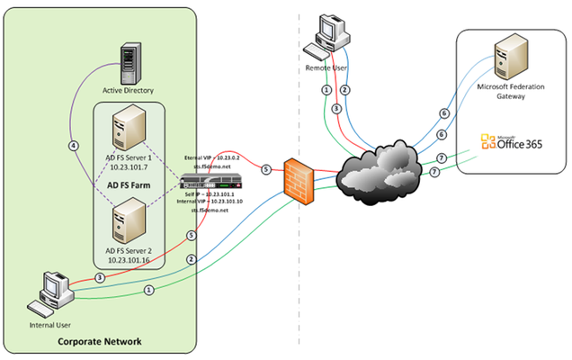
So let’s talk Application Delivery Controllers, (ADC). In part one of this series we deployed both an internal ADFS farm as well as a perimeter ADFS proxy farm using the Big-IP’s exceptional load balancing capabilities to provide HA and scalability. But there’s much more the Big-IP can provide to the application delivery experience. Here in part 2 we’ll utilize the Access Policy Manager, (APM) module as a replacement for the ADFS Proxy layer. To illustrate this approach, we’ll address one of the most common use cases; ADFS deployment to federate with and enable single sign-on to Microsoft Office 365 web-based applications. The purpose of the ADFS Proxy server is to receive and forward requests to ADFS servers that are not accessible from the Internet. As noted in part one, for high availability this typically requires a minimum of two proxy servers as well as an additional load balancing solution, (F5 Big-IPs of course). By implementing APM on the F5 appliance(s) we not only eliminate the need for these additional servers but, by implementing pre-authentication at the perimeter and advanced features such as client-side checks, (antivirus validation, firewall verification, etc.), arguably provide for a more secure deployment. Assumptions and Product Deployment Documentation - This deployment scenario assumes the reader is assumed to have general administrative knowledge of the BIG-IP LTM module and basic understanding of the APM module. If you want more information or guidance please check out F5’s support site, ASKF5. The following diagram shows a typical internal and external client access AD FS to Office 365 Process Flow, (used for passive-protocol, “web-based” access). Both clients attempts to access the Office 365 resource; Both clients are redirected to the resource’s applicable federation service, (Note: This step may be skipped with active clients such as Microsoft Outlook); Both client are redirected to their organization’s internal federation service; The AD FS server authenticates the client to active directory; * Internal clients are load balanced directly to an ADFS server farm member; and * External clients are: * Pre-authenticated to Active Directory via APM’s customizable sign-on page; *Authenticated users are directed to an AD FS server farm member. The ADFS server provides the client with an authorization cookie containing the signed security token and set of claims for the resource partner; The client connects to the Microsoft Federation Gateway where the token and claims are verified. The Microsoft Federation Gateway provides the client with a new service token; and The client presents the new cookie with included service token to the Office 365 resource for access. Virtual Servers and Member Pool – Although all users, (both internal and external) will access the ADFS server farm via the same Big-IP(s), the requirements and subsequent user experience differ. While internal authenticated users are load balanced directly to the ADFS farm, external users must first be pre-authenticated, (via APM) prior to be allowed access to an ADFS farm member. To accomplish this two, (2) virtual servers are used; one for the internal access and another dedicated for external access. Both the internal and external virtual servers are associated with the same internal ADFS server farm pool. INTERNAL VIRTUAL SERVER – Refer to Part 1 of this guidance for configuration settings for the internal ADFS farm virtual server. EXTERNAL VIRTUAL SERVER – The configuration for the external virtual server is similar to that of the virtual server described in Part 1 of this guidance. In addition an APM Access Profile, (see highlighted section and settings below) is assigned to the virtual server. APM Configuration – The following Access Policy Manager, (APM) configuration is created and associated with the external virtual server to provide for pre-authentication of external users prior to being granted access to the internal ADFS farm. As I mentioned earlier, the APM module provides advanced features such as client-side checks and single sign-on, (SSO) in addition to pre-authentication. Of course this is just the tip of the iceberg. Take a deeper look at client-side checks at AskF5. AAA SERVER - The ADFS access profile utilizes an Active Directory AAA server. ACCESS POLICY - The following access policy is associated with the ADFS access profile. * Prior to presenting the logon page client machines are checked for the existence of updated antivirus. If the client lacks either antivirus software or does not have updated, (within 30 days) virus definitions the user is redirected to a mitigation site. * An AD query and simple iRule is used to provide single-url OWA access for both on-premise and Office365 Exchange users. SSO CONFIGURATION - The ADFS access portal uses an NTLM v1 SSO profile with multiple authentication domains, (see below). By utilizing multiple SSO domains, clients are required to authenticate only once to gain access to both hosted applications such as Exchange Online and SharePoint Online as well as on-premise hosted applications. To facilitate this we deploy multiple virtual servers, (ADFS, Exchange, SharePoint) utilizing the same SSO configuration. CONNECTIVITY PROFILE – A connectivity profile based upon the default connectivity profile is associated with the external virtual server. Whoa! That’s a lot to digest. But if nothing else, I hope this inspires you to further investigate APM and some of the cool things you can do with the Big-IP beyond load balancing. Additional Links: Big-IP and ADFS Part 1 – “Load balancing the ADFS Farm” Big-IP and ADFS Part 3 - “ADFS, APM, and the Office 365 Thick Clients” BIG-IP Access Policy Manager (APM) Wiki Home - DevCentral Wiki Latest F5 Information F5 News Articles F5 Press Releases F5 Events F5 Web Media F5 Technology Alliance Partners F5 YouTube Feed4.2KViews0likes7CommentsHow to use Ansible with Cisco routers
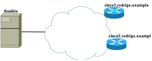
Quick Intro For those who don't know, there is an Ansible plugin callednetwork_clito retrieve network device configuration for backup, inspection and even execute commands. So, let's assume we have Ansible already installed and 2 routers: I used Debian Linux here and I had to install Python 3: I've also installed pip as we can see above because I wanted to install a specific version of Ansible (2.5.+) that would allow myself to use network_cli plugin: Note: we can list available Ansible versions by just typingpip install ansible== I've also created a user namedansible: Edited Linuxsudoersfile withvisudocommand: And addedAnsible user permission to run root commands without prompting for password so my file looked liked this: Quick Set Up This is my directory structure: These are the files I used for this lab test: Note: we can replace cisco1.rodrigo.example for an IP address too. In Ansible, there is a default config file (ansible.cfg) where we store the global config, i.e. how we want Ansible to behave. We also keep the list of our hosts into an inventory file (inventory.yml here). There is a default folder (group_vars) where we can store variables that would apply to any router we ran Ansible against and in this case it makes sense as my router credentials are the same. Lastly, retrieve_backup.yml is my actual playbook, i.e. where I tell Ansible what to do. Note: I manually logged in to cisco1.rodrigo.example and cisco2.rodrigo.example to populate ssh known_hosts files, otherwise Ansible complains these hosts are untrusted. Populating our Playbook file retrieve_backup.yml Let's say we just want to retrieve the OSPF configuration from our Cisco routers. We can useios_commandto type in any command to Cisco router and useregisterto store the output to a variable: Note: be careful with the indentation. I used 2 spaces here. We can then copy the content of the variable to a file in a given directory. In this case, we copied whatever is inospf_outputvariable toospf_configdirectory. From the Playbook file above we can work out that variables are referenced between{{ }}and we might probably be wondering why do we need to append stdout[0] to ospf_output right? If you know Python, you might be interested in knowing a bit more about what's going on under the hood so I'll clarify things a bit more here. The variableospf_outputis actually a dictionary andstdoutis one of its keys. In reality, ospf_output.stdout could be represented as ospf_output['stdout'] We add the[0] because the object retrieved by the key stdout is not a string. It's a list! And[0] just represents the first object in the list. Executing our Playbook I'll create ospf_config first: And we execute our playbook by issuingansible-playbookcommand: Now let's check if our OSPF config was retrieved: We can pretty much type in any IOS command we'd type in a real router, either to configure it or to retrieve its configuration. We could also append the date to the file name but it's out of the scope of this article. That's it for now.3.2KViews1like1CommentBig-IP and ADFS Part 4 – “What about Single Sign-Out?”
Why stop at 3 when you can go to 4? Over the past few posts on this ever-expanding topic, we’ve discussed using ADFS to provide single sign-on access to Office 365. But what about single sign-out? A customer turned me onto Tristan Watkins’ blog post that discusses the challenges of single sign-out for browser-based, (WS-Federation) applications when fronting ADFS with a reverse-proxy. It’s a great blog post and covers the topic quite well so I won’t bother re-hashing it here. However, I would definitely recommend reading his post if you want a deeper dive. Here’s the sign-out process: 1. User selects ‘Sign Out’ or ‘Sign in as Different User’, (if using SharePoint Online); 2. The user is signed out of the application; 3. The user is redirected to the ADFS sign out page; and 4. The user is redirected back to the Microsoft Federation Gateway and the user’s tokens are invalidated. In a nutshell, claims-unaware proxies, (Microsoft ISA and TMG servers for example) are unable to determine when this process has occurred and subsequently the proxy session remains active. This in turn will allow access to ADFS, (and subsequently Office 365) without be prompted for new credentials, (not good!). Here’s where I come clean with you dear readers. While the F5 Big-IP with APM is a recognized replacement for the AD FS 2.0 Federation Server Proxy this particular topic was not even on my radar. But now that it is…… Single Sign-Out with Access Policy Manager You’ll may have noticed that although the Big-IP with APM is a claims-unaware proxy I did not include it in the list above. Why you ask? Well, although the Big-IP is currently “claims-unaware”, it certainly is “aware” of traffic that passes through. With the ability to analyze traffic as it flows from both the client and the server side, the Big-IP can look for triggers and act upon them. In the case of the ADFS sign-out process, we’ll use the MSISSignOut cookie as our trigger to terminate the proxy session accordingly. During the WS-Federation sign out process, (used by browser-based applications) the MSISSignOut cookie is cleared out by the ADFS server, (refer to the HttpWatch example below). Once this has been completed, we need to terminate the proxy session. Fortunately, there’s an iRule for that. The iRule below analyzes the HTTP response back from the ADFS server and keys off of the MSISSignOut cookie. If the cookie’s value has been cleared, the APM session will be terminated. To allow for a clean sign-out process with the Microsoft Federation Gateway, the APM session termination is delayed long enough for the ADFS server to respond. Now, APM’s termination can act in concert with the ADFS sign-out process. 1: when HTTP_RESPONSE { 2: # Review server-side responses for reset of WS-Federation sign-out cookie - MSISSignOut. 3: # If found assign ADFS sign-out session variable and close HTTP connection 4: if {[HTTP::header "Set-Cookie"] contains "MSISSignOut=;"} { 5: ACCESS::session data set session.user.adfssignout 1 6: HTTP::close 7: } 8: } 9: 10: when CLIENT_CLOSED { 11: # Remove APM session if ADFS sign-out variable exists 12: if {[ACCESS::session data get session.user.adfssignout] eq 1} { 13: after 5000 14: ACCESS::session remove 15: } 16: } What? Another iRule? Actually, the above snippet can be combined with the iRule we implemented in Part 3 creating a single iRule addressing all the ADFS/Office 365 scenarios. 1: when HTTP_REQUEST { 2: # For external Lync client access all external requests to the 3: # /trust/mex URL must be routed to /trust/proxymex. Analyze and modify the URI 4: # where appropriate 5: HTTP::uri [string map {/trust/mex /trust/proxymex} [HTTP::uri]] 6: 7: # Analyze the HTTP request and disable access policy enforcement WS-Trust calls 8: if {[HTTP::uri] contains "/adfs/services/trust"} { 9: ACCESS::disable 10: } 11: 12: # OPTIONAL ---- To allow publishing of the federation service metadata 13: if {[HTTP::uri] ends_with "FederationMetadata/2007-06/FederationMetadata.xml"} { 14: ACCESS::disable 15: } 16: } 17: 18: when HTTP_RESPONSE { 19: # Review serverside responses for reset of WS-Federation sign-out cookie - MSISSignOut. 20: # If found assign ADFS sign-out session variable and close HTTP connection 21: if {[HTTP::header "Set-Cookie"] contains "MSISSignOut=;"} { 22: ACCESS::session data set session.user.adfssignout 1 23: HTTP::close 24: } 25: } 26: 27: when CLIENT_CLOSED { 28: # Remove APM session if ADFS sign-out variable exists 29: if {[ACCESS::session data get session.user.adfssignout] eq 1} { 30: after 5000 31: ACCESS::session remove 32: } 33: } Gotta love them iRules! That’s all for now. Additional Links: Big-IP and ADFS Part 1 – “Load balancing the ADFS Farm” Big-IP and ADFS Part 2 – “APM–An Alternative to the ADFS Proxy” Big-IP and ADFS Part 3 – “ADFS, APM, and the Office 365 Thick Clients” BIG-IP Access Policy Manager (APM) Wiki Home - DevCentral Wiki AD FS 2.0 - Interoperability with Non-Microsoft Products MS TechNet - AD FS: How to Invoke a WS-Federation Sign-Out Tristan Watkins - Office 365 Single Sign Out with ISA or TMG as the ADFS Proxy Technorati Tags: load balancer,ADFS,Office365,active directory,F5,federation,exchange,microsoft,network,blog,APM,LTM,Coward,SSO,single sign-on,single sign-out928Views0likes2CommentsWAN Optimization is not Application Acceleration
Increasingly WAN optimization solutions are adopting the application acceleration moniker, implying a focus that just does not exist. WAN optimization solutions are designed to improve the performance of the network, not applications, and while the former does beget improvements of the latter, true application acceleration solutions offer greater opportunity for improving efficiency and end-user experience as well as aiding in consolidation efforts that result in a reduction in operating and capital expenditure costs. WAN Optimization solutions are, as their title implies, focused on the WAN; on the network. It is their task to improve the utilization of bandwidth, arrest the effects of network congestion, and apply quality of service policies to speed delivery of critical application data by respecting application prioritization. WAN Optimization solutions achieve these goals primarily through the use of data de-duplication techniques. These techniques require a pair of devices as the technology is most often based on a replacement algorithm that seeks out common blocks of data and replaces them with a smaller representative tag or indicator that is interpreted by the paired device such that it can reinsert the common block of data before passing it on to the receiver. The base techniques used by WAN optimization are thus highly effective in scenarios in which large files are transferred back and forth over a connection by one or many people, as large chunks of data are often repeated and the de-duplication process significantly reduces the amount of data traversing the WAN and thus improves performance. Most WAN optimization solutions specifically implement “application” level acceleration for protocols aimed at the transfer of files such as CIFS and SAMBA. But WAN optimization solutions do very little to aid in the improvement of application performance when the data being exchanged is highly volatile and already transferred in small chunks. Web applications today are highly dynamic and personalized, making it less likely that a WAN optimization solution will find chunks of duplicated data large enough to make the overhead of the replacement process beneficial to application performance. In fact, the process of examining small chunks of data for potential duplicated chunks can introduce additional latency that actual degrades performance, much in the same way compression of small chunks of data can be detrimental to application performance. Too, WAN optimization solutions require deployment in pairs which results in what little benefits these solutions offer for web applications being enjoyed only by end-users in a location served by a “remote” device. Customers, partners, and roaming employees will not see improvements in performance because they are not served by a “remote” device. Application acceleration solutions, however, are not constrained by such limitations. Application acceleration solutions act at the higher layers of the stack, from TCP to HTTP, and attempt to improve performance through the optimization of protocols and the applications themselves. The optimizations of TCP, for example, reduce the overhead associated with TCP session management on servers and improve the capacity and performance of the actual application which in turn results in improved response times. The understanding of HTTP and both the browser and server allows application acceleration solutions to employ techniques that leverage cached data and industry standard compression to reduce the amount of data transferred without requiring a “remote” device. Application acceleration solutions are generally asymmetric, with some few also offering a symmetric mode. The former ensures that regardless of the location of the user, partner, or employee that some form of acceleration will provide a better end-user experience while the latter employs more traditional WAN optimization-like functionality to increase the improvements for clients served by a “remote” device. Regardless of the mode, application acceleration solutions improve the efficiency of servers and applications which results in higher capacities and can aid in consolidation efforts (fewer servers are required to serve the same user base with better performance) or simply lengthens the time available before additional investment in servers – and the associated licensing and management costs – must be made. Both WAN optimization and application acceleration aim to improve application performance, but they are not the same solutions nor do they even focus on the same types of applications. It is important to understand the type of application you want to accelerate before choosing a solution. If you are primarily concerned with office productivity applications and the exchange of large files (including backups, virtual images, etc…) between offices, then certainly WAN optimization solutions will provide greater benefits than application acceleration. If you’re concerned primarily about web application performance then application acceleration solutions will offer the greatest boost in performance and efficiency gains. But do not confuse WAN optimization with application acceleration. There is a reason WAN optimization-focused providers have recently begun to partner with application acceleration and application delivery providers – because there is a marked difference between the two types of solutions and a single offering that combines them both is not (yet) available.773Views0likes2CommentsWILS: Network Load Balancing versus Application Load Balancing
Are you load balancing servers or applications? Network traffic or application requests? If your strategy to application availability is network-based you might need a change in direction (up the stack). Can you see the application now? Network load balancing is the distribution of traffic based on network variables, such as IP address and destination ports. It is layer 4 (TCP) and below and is not designed to take into consideration anything at the application layer such as content type, cookie data, custom headers, user location, or the application behavior. It is context-less, caring only about the network-layer information contained within the packets it is directing this way and that. Application load balancing is the distribution of requests based on multiple variables, from the network layer to the application layer. It is context-aware and can direct requests based on any single variable as easily as it can a combination of variables. Applications are load balanced based on their peculiar behavior and not solely on server (operating system or virtualization layer) information. The difference between the two is important because network load balancing cannot assure availability of the application. This is because it bases its decisions solely on network and TCP-layer variables and has no awareness of the application at all. Generally a network load balancer will determine “availability” based on the ability of a server to respond to ICMP ping, or to correctly complete the three-way TCP handshake. An application load balancer goes much deeper, and is capable of determining availability based on not only a successful HTTP GET of a particular page but also the verification that the content is as was expected based on the input parameters. This is also important to note when considering the deployment of multiple applications on the same host sharing IP addresses (virtual hosts in old skool speak). A network load balancer will not differentiate between Application A and Application B when checking availability (indeed it cannot unless ports are different) but an application load balancer will differentiate between the two applications by examining the application layer data available to it. This difference means that a network load balancer may end up sending requests to an application that has crashed or is offline, but an application load balancer will never make that same mistake. WILS: Write It Like Seth. Seth Godin always gets his point across with brevity and wit. WILS is an ATTEMPT TO BE concise about application delivery TOPICS AND just get straight to the point. NO DILLY DALLYING AROUND. WILS: InfoSec Needs to Focus on Access not Protection WILS: Applications Should Be Like Sith Lords WILS: Cloud Changes How But Not What WILS: Application Acceleration versus Optimization WILS: Automation versus Orchestration Layer 7 Switching + Load Balancing = Layer 7 Load Balancing Business-Layer Load Balancing Not all application requests are created equal Cloud Balancing, Cloud Bursting, and Intercloud The Infrastructure 2.0 Trifecta713Views0likes0CommentsF5 Friday: Goodbye Defense in Depth. Hello Defense in Breadth.
#adcfw #infosec F5 is changing the game on security by unifying it at the application and service delivery layer. Over the past few years we’ve seen firewalls fail repeatedly. We’ve seen business disrupted, security thwarted, and reputations damaged by the failure of the very devices meant to prevent such catastrophes from happening. These failures have been caused by a change in tactics from invaders who seek no longer to find away through or over the walls, but who simply batter it down instead. A combination of traditional attacks – network-layer – and modern attacks – application-layer – have become a force to be reckoned with; one that traditional stateful firewalls are often not equipped to handle. Encrypted traffic flowing into and out of the data center often bypasses security solutions entirely, leaving another potential source of a breach unaddressed. And performance is being impeded by the increasing number of devices that must “crack the packet” as it were and examine it, often times duplicating functionality with varying degrees of success. This is problematic because the resolution to this issue can be as disconcerting as the problem itself: disable security. Seriously. Security functions have been disabled, intentionally, in the name of performance. IT security personnel within large corporations are shutting off critical functionality in security applications to meet network performance demands for business applications. SURVEY: SECURITY SACRIFICED FOR NETWORK PERFORMANCE What the company [NSS Labs] found would likely startle any existing or potential customers: three of the six firewalls failed to stay operational when subjected to stability tests, five out of six didn't handle what is known as the "Sneak ACK attack," that would enable attackers to side-step the firewall itself. Finally, according to NSS Labs, the performance claims presented in the vendor datasheets "are generally grossly overstated." Independent lab tests find firewalls fall down on the job Add in the complexity from the sheer number of devices required to implement all the different layers of security needed, which increases costs while impairing performance, and you’ve got a broken model in need of repair. This is a failure of the defense in depth strategy; the layered, multi-device (silo) approach to operational security. Most importantly, it’s one that’s failing to withstand attacks. What we need is defense in breadth – the height of the stack –to assure availability and security using a more intelligent, unified security strategy. DEFENSE in BREADTH While it’s really not as catchy as “defense in the depth” the concept behind the admittedly awkward sounding phrase is sound: to assure availability and security simultaneously requires a strong security strategy from the bottom to the top of the networking stack, i.e. the application layer. The ability of the F5 BIG-IP platform to provide security up and down the stack has existed for many years, and its capabilities to detect, prevent, and withstand concerted attacks has been appreciated by its customers (quietly) for some time. While basic firewalling functions have been a part of BIG-IP for years, there are certain capabilities required of a firewall – specifically an ICSA certified firewall – that it didn’t have. So we decided to do something about that. The result is the ICSA certification of the BIG-IP platform as a network firewall. Combined with its existing ICSA certification for web application firewall (BIG-IP Application Security Manager) and SSL-TLS VPN 3.0 (BIG-IP Edge Gateway), the BIG-IP platform now supports a full-spectrum security solution in a single, unified system. What is unique about F5’s approach is that the security capabilities noted above can be deployed on BIG-IP Application Delivery Controllers (ADCs)—best known for providing industry-leading intelligent traffic management and optimization capabilities. This firewall solution is part of F5’s comprehensive security architecture that enables customers to apply a unified security strategy. For the first time in the industry, organizations can secure their networks, data, protocols, applications, and users on a single, flexible, and extensible platform: BIG-IP. Combining network-firewall services with the ability to plug the hole in modern security implementations (the application layer) with a platform-based solution provides the opportunity to consolidate security services and leverage a shared infrastructure platform resulting in a more comprehensive, strategic deployment that is not only more secure, but more cost effective. Resources: The Fundamental Problem with Traditional Inbound Protection The Ascendancy of the Application Layer Threat ISCA Certified Network Firewall for Data Centers Mature Security Organizations Align Security with Service Delivery BIG-IP Data Center Firewall Solution – SlideShare Presentation The New Data Center Firewall Paradigm – White Paper Independent lab tests find firewalls fall down on the job SURVEY: SECURITY SACRIFICED FOR NETWORK PERFORMANCE F5 Friday: When Firewalls Fail… Challenging the Firewall Data Center Dogma What We Learned from Anonymous: DDoS is now 3DoS The Many Faces of DDoS: Variations on a Theme or Two F5 Friday: Eliminating the Blind Spot in Your Data Center Security Strategy F5 Friday: Multi-Layer Security for Multi-Layer Attacks522Views0likes0CommentsSDN Network Models
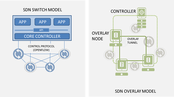
#SDN models: switches and overlays As with most new exciting (read: hyped) technology there's always some initial fragmentation that occurs in the market. Everyone wants to have their fingers in the newest pie and from that comes what musicians call "variations on a theme." The melody is the same, but the harmony and chords are enough different so as to make them appear to be different songs. SDN is no different, and there is already some fragmentation in the basic SDN model. While ONF continues to focus on the "original" switch-based model, offerings that instead use an overlay-model are beginning to get noticed. Not to belabor one of my favorite quotes this year but... "If you look at the standard SDN model, [Layer 4-7 services] are applications that can basically run on the [SDN] controller platform. But that's not the only way to do them. We'll hear about different approaches. Network services for SDN are going to be a big story in 2013." -- Brad Casemore, "Networking outlook: Controllers, Layer 4-7 will roil SDN 2013 market" [emphasis mine] It's not just the L4-7 services that can be done "differently" then the first incarnation of SDN. It's L2-3, too, that will ultimately fragment into 2 or 3 core models, each designed to solve the same problem but having different architectural and business benefits. For example, the switch-based SDN model relies heavily on standardization and commoditization in the network. Today that means OpenFlow-enabled switching fabrics running on commoditized hardware (note that this overlaps well with the notion of network virtualization in general, because the OpenFlow-enabled switches could be virtual or physical, depending on desire and need). This model, however, is somewhat disruptive and capital intensive, because it requires investment in the switching fabric. That may mean upgrades to firmware or new hardware. Either way, it's disruptive. The benefits of the disruption include agility, lower operational overhead than is incurred by managing your network node by node, and a network that is ostensibly more resilient and able to adapt without human intervention. The overlay model, on the other hand, benefits primarily from being non-disruptive. It assumes an existing, L3 IP fabric atop which it lays its own, virtual network using tunneling methodologies. Solutions like Midokura's MidoNet, VMware's Nicira and VXLAN, and Microsoft's NVGRE are overlay-based SDN models that seek to minimize disruption while enabling a physically agnostic network topology that is better suited for cloud and agile infrastructure. The flip side, of course, is that you're now managing two completely different networks, which is necessarily going to have an impact on operational overhead. Neither of the models is perfect, and I'm sure someone from each "side" would argue the other isn't really SDN. But the notion behind SDN is to address some very real problems around network rigidity and reliance on fixed IP network strategies. Both do that, just in different ways.520Views0likes0Comments