f5 distributed cloud
242 TopicsF5 Distributed Cloud Multi-Cloud Networking Lab - Part 3: Multi-Site
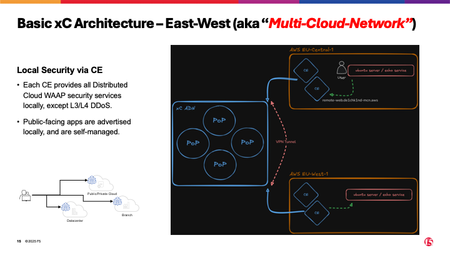
Series: F5 Distributed Cloud Multi-Cloud Networking Lab Previous: Part 2: Hybrid - RE + CE Architecture Next: Part 4: Use Cases - North-South RE-Only & RE-to-CE (TBD) Beyond North-South The SaaS and Hybrid models solve the north-south problem: how do external users reach your application securely? But modern architectures have a second problem that is often harder to solve: east-west traffic. Applications calling APIs in other regions. Microservices communicating across data centers. Backend systems in Frankfurt that need to reach a service in Dublin. This is east-west traffic, and traditionally it requires VPN tunnels, Transit Gateways, VPC peering, MPLS circuits, or some combination of all four. The Multi-Site model takes a different approach. Instead of building point-to-point connections between your environments, you deploy Customer Edge nodes at each site and let the xC fabric handle the rest. The CE as a Full Application Delivery Node In the Hybrid model, the CE serves as an egress point - a gateway between the xC fabric and your private network. In the Multi-Site model, the CE takes on a larger role. It becomes a complete application proxy that can: Terminate TLS locally - no round-trip to the RE for every request Apply WAF policies - the same engine that runs on the RE, now running at your site Advertise load balancers on its own interfaces - both internal (SLi) and external (SLo via NLB) Route traffic to other CEs through the xC fabric - encrypted, optimized, without VPN configuration Discover services - Kubernetes, DNS, IP-based discovery on the local network Run container workloads - via Virtual Kubernetes (vk8s), managed from the xC console This is the conceptual shift: in Multi-Site, you are not just extending the F5 Global Network into your environment - you are building your own private PoPs. How It Works CE-Direct (North-South Without RE) In some scenarios, you want the load balancer to run **directly on the CE** - not on the RE. External users connect to the CE (via a cloud load balancer like AWS NLB), and the CE handles TLS termination, WAF inspection, and backend forwarding locally. Why would you skip the RE? Latency: Traffic does not need to traverse the global PoP network before reaching your site Data residency: Traffic never leaves your cloud region - it enters the CE directly Internal + external access: The same LB can serve both external clients (via NLB) and internal clients (via private DNS resolving to the CE's SLi interface) The traffic path for CE-direct: External user → AWS NLB → CE → WAF → Private backend Internal user → Route53 (private zone) → CE → WAF → Private backend Both paths hit the same xC load balancer on the CE, with the same WAF policy applied. The CE does not distinguish between external and internal clients - it applies the same security posture to both. CE-to-CE (East-West) This is where the Multi-Site model unlocks its full potential. Two CEs in different regions can communicate through the xC fabric without any traditional networking infrastructure between them. The traffic path for east-west: App in Frankfurt → CE (eu-central) → xC Fabric → CE (eu-west) → App in Dublin No VPC peering. No Transit Gateway (between regions). No VPN tunnels. No MPLS. The CEs handle encryption, routing, and load balancing. The xC fabric provides the transport. What makes this powerful is the abstraction: the application in Frankfurt simply makes a request to a hostname (e.g., `remote-web.lab.example.com`). The CE resolves it locally, applies the configured policy, and routes it through the fabric to the appropriate destination. The application does not know or care that the backend is in a different region. Advertise Modes The way a load balancer is exposed depends on its **advertise mode** - a configuration that tells xC where to make the LB available: Mode Where It Runs Accessible From Use Case advertise_on_internet RE (all PoPs)* Internet (anycast) SaaS model, public apps advertise_custom on CE, SITE_NETWORK_INSIDE_AND_OUTSIDE CE (specific sites) Both internal network and external (e.g. via NLB) CE-direct, dual access advertise_custom on CE, SITE_NETWORK_INSIDE CE (specific sites) Internal network only East-west, private services * Can be further limited to certain PoPs This is a key concept in xC: the same load balancer definition (origin pool, WAF policy, certificate) can be advertised in different modes depending on where you want it to be reachable. Change the advertise mode, and the same LB moves from the global edge to a local CE - or vice versa. Service Discovery and Edge Compute Leveraging Customer Edges opens two additional capabilities that are not available in SaaS: Kubernetes Service Discovery If your applications run in Kubernetes clusters, the CE can discover services automatically. You register a kubeconfig with xC, and the platform creates a service discovery object that watches for services matching your criteria. Origin pools can then reference discovered services instead of static IPs. This means: deploy a new service in your k8s cluster, and xC picks it up automatically. No manual origin pool updates, no re-deployment of load balancers. In the lab, this is demonstrated with minikube clusters running on the Ubuntu servers. The kubeconfig is extracted via SSH, registered with xC, and used to create origin pools that discover echo services dynamically. Virtual Kubernetes (vk8s) The most advanced Multi-Site capability: running container workloads directly on the CE without a separate Kubernetes cluster. xC provides a managed Kubernetes control plane (vk8s), and the CE acts as the worker node. You define workloads in the xC console, container image, resource limits, replicas, and xC deploys them to the CE. The CE runs the pods alongside its proxy functions. This turns every CE into an edge compute node, managed centrally. In the lab, a vk8s cluster is created across two regions, an echo workload is deployed, and HTTP load balancers expose it - all via API calls. No kubectl, no cluster management, no node provisioning. How This Looks in the Lab The Multi-Site model maps to four lab use cases: CE via Cloud-Load-Balancer (CE-Direct, North-South) Pattern: External NLB → CE → Private backend Advertise mode: advertise_custom, SITE_NETWORK_INSIDE_AND_OUTSIDE Key insight: Same LB serves both external traffic (via NLB) and internal traffic (via Route53 private zone). WAF runs on the CE, not the RE. External: User → NLB → CE → WAF → Echo server Internal: App → Route53 → CE (SLi) → WAF → Echo server CE to CE (East-West) Pattern: CE (region A) → xC Fabric → CE (region B) → Backend Advertise mode: advertise_custom, SITE_NETWORK_INSIDE Key insight: Both LBs share the same FQDN (`remote-web.{domain}`) but are scoped to different CEs. An app in Frankfurt sees a load balancer that routes to Dublin. An app in Dublin sees a load balancer that routes to Frankfurt. Same hostname, different destinations based on locality. Frankfurt app → CE (eu-central) → xC Fabric → CE (eu-west) → Dublin echo server Dublin app → CE (eu-west) → xC Fabric → CE (eu-central) → Frankfurt echo server k8s Service Discovery Pattern: RE → CE → k8s service (discovered via kubeconfig) Key insight: Origin pools use dynamic service discovery instead of static IP addresses. New services are detected automatically. vk8s Edge Computing Pattern: RE → CE (running the workload itself) Key insight: The CE is both the proxy and the compute node. No external Kubernetes cluster needed. When to Use the Multi-Site Model The Multi-Site model is the right choice when: You need east-west connectivity between regions or data centers without VPN/peering complexity You want WAF and security policies enforced locally at each site, not just at the global edge Latency matters - local TLS termination and WAF inspection reduce round-trip times You need dual access (internal + external) to the same service with consistent policies You want to run edge compute workloads on CE nodes without managing Kubernetes clusters You are consolidating VPN/MPLS/Transit Gateway setups into a single platform When to Stay with Hybrid If your traffic pattern is purely north-south (external users to private backends) and you do not need east-west or local WAF, the Hybrid model is simpler and sufficient. The Multi-Site model adds capabilities but also adds CE complexity. The Three Models Side by Side Aspect SaaS (RE-Only) Hybrid (RE + CE) Multi-Site (CE-Only/CE+CE) Ingress RE RE CE (or RE) Egress Internet CE CE WAF runs on RE RE CE (and/or RE) East-west No Yes - CE deployed, basis is set Yes CE required No Yes Yes Edge compute No Yes - CE deployed, basis is set Yes (vk8s) Origin visibility Public Private (CE-local) Private (CE-local) Complexity Low Medium Medium-to-High Best for Public apps, PoC Private backends, compliance Multi-region, east-west, edge Key Takeaways The Multi-Site model turns the CE from a gateway into a full application delivery node East-west traffic between CEs flows through the xC fabric - no VPN, no peering, no MPLS Advertise modes control where a load balancer is reachable (RE, CE inside, CE outside, or both) Service discovery and vk8s are Multi-Site capabilities that extend xC beyond networking into service mesh and edge compute territory All three models share the same policy engine - a WAF policy written for SaaS works identically on a CE in the Multi-Site model Up Next With the architecture foundations covered, the next articles shift from concepts to implementation. Each use case article walks through the actual deployment - API calls, JSON payloads, verification commands, and the exact traffic path through the lab. Part 4: Use Cases - North-South: RE-Only & RE-to-CE (TBD) - Deploying the two foundational north-south patterns, from certificate generation to load balancer creation.21Views2likes0CommentsF5 Distributed Cloud Multi-Cloud Networking Lab - Part 2: Hybrid
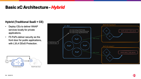
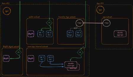
Series: F5 Distributed Cloud Multi-Cloud Networking Lab Previous: Part 1: SaaS - RE-Only Architecture Next: Part 3: Multi-Site - CE-Only Architecture When Public Is Not an Option The SaaS model works well for applications with publicly reachable backends. But in practice, many workloads run in private subnets - behind firewalls, in VPCs without internet-facing load balancers, or in on-premises data centers that are deliberately isolated from the internet. These applications still need global load balancing, WAF protection, and DDoS mitigation. They just cannot expose their origins publicly. This is the problem the Hybrid model solves. It keeps everything that makes the SaaS model effective - global anycast ingress, WAF at the edge, centralized policy management; and adds a private path from the F5 Global Network into your environment. That private path is the Customer Edge (CE). The Customer Edge A Customer Edge is a lightweight node, a virtual machine or bare-metal appliance, that you deploy in your own environment. It runs wherever your applications run: in an AWS VPC, an Azure VNet, a GCP project, or an on-premises data center. What makes the CE different from a traditional reverse proxy or VPN gateway: Outbound-only connectivity: The CE initiates connections to the F5 Global Network. No inbound firewall rules required. No public IPs on the CE. No VPN configuration. Automatic mesh: Once registered, the CE joins the xC fabric - an encrypted overlay network that connects all REs and CEs. Traffic between any two points in the fabric is encrypted and optimized. Full proxy capabilities: The CE can terminate TLS, apply WAF policies, discover local services, and forward traffic to private backends. It is not just a tunnel endpoint - it is a complete application delivery node. In the Hybrid model, the CE acts as the egress point: traffic enters via the RE (global anycast), traverses the xC fabric, and exits through the CE into your private network. How It Works A user makes a request to the application's FQDN DNS resolves to xC's anycast IP - the user connects to the nearest Regional Edge The RE terminates TLS and applies WAF, Bot, and DDoS policies - identical to the SaaS model The RE forwards the request through the xC fabric to the Customer Edge in the target region The CE receives the request and forwards it to the private backend (e.g., a server in a VPC private subnet) The response travels back through the CE → xC fabric → RE → user The critical difference from SaaS: step 4 and 5 replace the internet egress. Instead of the RE connecting to a public origin over the internet, it routes through the private xC fabric to a CE that has local network access to the backend. Why This Matters No Public Exposure The backend never needs a public IP, a public load balancer, or an internet-facing security group. The CE connects to backends using private IPs on the local network. From the backend's perspective, traffic comes from the CE — a trusted, local source. No Inbound Firewall Rules Traditional hybrid architectures require opening inbound ports for VPN tunnels or reverse proxy connections. The CE reverses this: it initiates outbound connections to the xC fabric. Your firewall only needs to allow outbound HTTPS (port 443) and IPSec/IPSEC-NAT-T (ports 500, 4500). No inbound rules, no NAT hairpinning, no DMZ configurations. Consistent Security The WAF policy you apply in the SaaS model works identically in the Hybrid model. The RE still inspects traffic at the edge. The only difference is where the traffic goes after inspection. This means you can start with SaaS for a public-facing application and later move it behind a CE without changing your security configuration. Origin Discovery via CE In the Hybrid model, origin pools reference backends that are only reachable from the CE's local network. Discovery methods include: Private IP - direct IP address of the backend server Private DNS - hostname resolved by the CE on the local network (e.g., Route53 private hosted zone) Kubernetes service - service name in a local k8s cluster (later use case) The CE acts as the resolver and forwarder. The RE does not need to know the backend's IP - it only needs to know which CE site to route to. Multi-NIC: Inside and Outside In many environments, the CE is deployed with two network interfaces: Interface Name Connected To Purpose SLo (Site Local Outside) Public / Internet-facing Public subnet, Internet Gateway, (application servers) Connects to the xC fabric, receives management traffic SLi (Site Local Inside) Private / Backend-facing Private subnet, application servers Forwards traffic to local backends This dual-NIC architecture provides network segmentation: the SLo interface faces the internet (for fabric connectivity), while the SLi interface faces the private network (for backend access). Traffic from the xC fabric arrives on SLo and exits to the backend via SLi. In the lab environment, the CE's SLo interface sits in the public subnet with an Elastic IP, and the SLi interface sits in the private subnet alongside the Ubuntu servers and BIG-IP appliances. A Transit Gateway connects the Main VPC to the App VPC, extending the CE's reach to application workloads in a separate network segment. For a more simplistic set up, or a Proof of Concecpt, the SLo can be used for inside and outside traffic (Single-NIC). How This Looks in the Lab** The Hybrid model maps to several lab use cases, but the most direct demonstration is the RE-to-CE use case: Ingress: RE (global anycast) Egress: CE in `eu-central-1` and/or `eu-west-1` Backends: Ubuntu echo servers on private IPs, discovered via origin pools created during infrastructure provisioning Configuration: Three load balancers demonstrate different routing strategies: Load Balancer Origin Pool Behavior lb-echo-hybrid Both regions Multi-region - xC routes to the app defined as lb-logic (e.g. round robin) lb-echo-hybrid-central eu-central-1 only Regional pinning - all traffic exits in Frankfurt lb-echo-hybrid-west eu-west-1 only Regional pinning - all traffic exits in Ireland ** This is a preview to the use case later in the lab The traffic path: User → Nearest RE → WAF → xC Fabric → CE (eu-central or eu-west) → Private subnet → Echo server Regional Pinning vs. Multi-Region This is a practical consideration that comes up in real deployments. The multi-region LB lets xC decide which CE to use based on proximity, health, and load. It supports migration and scale out scenarios. With policies, admins can control who access which region (A/B Testing/Canary Releases by ratio, cookie or header; access policy by Source IP, ...). The pinned LBs force all traffic to a specific region - useful when data residency requirements mandate that traffic exits in a particular geography. Both configurations use the same WAF policy, the same certificate management, and the same origin pool structure. The only difference is the origin_servers_subset in the load balancer configuration. The BIG-IP Extension The lab includes a second Hybrid use case: RE-to-CE via BIG-IP. This extends the traffic path by one hop: User → RE → WAF → xC Fabric → CE → BIG-IP → Echo server This is the "better together" scenario - xC handles global ingress, anycast, and WAF at the edge. The CE provides private network access. And BIG-IP adds local traffic management capabilities: iRules, advanced health monitors, connection persistence, or APM policies. In the lab, the BIG-IP is configured with an AS3 virtual server that accepts TLS traffic from the CE and applies an iRule injecting custom headers. It demonstrates that xC does not replace BIG-IP - it extends it with a global front door. This set up (as we chain services) would also work in a SaaS only set up. But in many environments it invoilved the CE to build a "private switch" to access private apps directly or go via a BIG-IP. When to Use the Hybrid Model The Hybrid model is the right choice when: Your application runs in a private subnet without public internet access Compliance requirements prevent exposing backend servers to the internet You want consistent WAF policies across public and private applications You need to consolidate multiple tools (external LB + WAF + VPN) into one platform You are integrating existing BIG-IP deployments with a modern global delivery layer When to Consider Multi-Site Instead If your use case involves east-west traffic between sites (not just north-south from users to backends), or if you want the load balancer to run directly on the CE without RE involvement, the Multi-Site model is the next step. Key Takeaways Aspect Hybrid / RE + CE Ingress Regional Edge (anycast) Egress Customer Edge (private network) CE Required Yes Origin Visibility Private — only CE needs local access WAF Location RE (edge) Fabric Encrypted overlay (RE → CE) Best For Private backends, compliance, hybrid environments Up Next Part 3: Multi-Site - CE-Only Architecture - What happens when you remove the RE from the equation entirely? Customer Edges become full application delivery nodes - with local WAF, east-west routing, and edge compute.59Views1like0CommentsF5 Distributed Cloud Multi-Cloud Networking Lab - Part 1: SaaS
Series: F5 Distributed Cloud Multi-Cloud Networking Lab Previous: Hub - MCN Lab Overview Next: Part 2: Hybrid - RE + CE Architecture The Simplest Path to Application Delivery Every distributed cloud platform needs a starting point - a model that delivers value without requiring you to deploy anything in your own environment. For F5 Distributed Cloud, that starting point is the SaaS model, also called the RE-Only architecture. RE stands for Regional Edge - the nodes that make up F5's global network of Points of Presence (PoPs). When you use the SaaS model, your application traffic flows entirely through this network. No Customer Edge. No on-premises deployment. No VPN tunnels. It is the architecture most people associate with a cloud-based WAF or CDN provider. But within the xC platform, it is just one of three deployment models - and the one that everything else builds on. How It Works The traffic flow in the SaaS model is straightforward: A user makes a request to your application's FQDN (e.g., echo-public.lab.example.com) DNS resolves to xC's anycast IP - the user is automatically routed to the nearest Regional Edge The RE terminates TLS, applies the configured security policies (WAF, Bot Defense, DDoS mitigation), and inspects the request The RE forwards the request to the origin server over the public internet The origin responds, and the RE delivers the response back to the user The key characteristic: both ingress and egress happen at the Regional Edge. The RE connects to your backend the same way any external client would: over the internet, typically via a public load balancer, a cloud NLB, or a direct public IP. Customers can than set up an ACL on their edge router to block everything not related to F5 XC and ensure no "non-xc-filtered" traffic cann access the application. What the RE Provides A Regional Edge is not a simple proxy. Each PoP is a full-stack application delivery node: Global Anycast Every HTTP load balancer you create on xC is automatically advertised on the platform's anycast IP across all PoPs worldwide. Users connect to the geographically closest edge - no manual DNS configuration, no geo-routing rules, no latency-based health checks. The network handles it. TLS Termination The RE terminates TLS at the edge. You can use xC-managed certificates (automatic Let's Encrypt), upload your own certificates, or, as this lab does, generate CA-signed certificates and upload them via the API. The backend connection can be re-encrypted (TLS to origin) or plain HTTP, depending on your requirements. Web Application Firewall The WAF runs at the RE, inspecting every request before it reaches your origin. In this lab, the WAF is configured in blocking mode with: OWASP Top 10 signature coverage Threat campaign detection (proactive zero-day protection) Custom blocking page Full request logging for visibility The same WAF policy can later be applied to Hybrid and Multi-Site deployments without modification. Write it once, enforce it everywhere. Origin Discovery In the SaaS model, the RE needs to know where to send traffic. This is configured via Origin Pools - a list of backends identified by: FQDN (DNS name, e.g., an AWS NLB DNS name) IP address** (direct) Kubernetes service (for later models) Since the RE connects over the internet, origins must be publicly reachable. This is the primary constraint of the SaaS model and the reason the Hybrid model exists. When to Use the SaaS Model The SaaS model is the right choice when: Your application has a publicly reachable origin (behind a cloud LB, CDN, or public IP) You want WAF, DDoS, and bot protection without deploying any infrastructure You need to be live in minutes - create a load balancer, point DNS, done You're looking for a quick proof-of-concept before committing to a deeper integration It is also the natural first step in a progressive adoption: start with SaaS for public-facing applications, then extend to Hybrid for private backends, and Multi-Site for cross-region east-west traffic. Same console, same policies, no re-architecture required. When NOT to Use It The SaaS model has one fundamental limitation: the origin must be internet-reachable. If your backend runs in a private subnet, behind a firewall, or in a data center without public exposure, the RE cannot reach it. That is where the Hybrid model with Customer Edge comes in. How This Looks in the Lab (later chapter) In the lab environment, the SaaS model maps to the RE-Only use case: Origin: AWS Network Load Balancers (NLBs) fronting Ubuntu echo servers in two regions Discovery: The origin pool uses the NLB FQDN - the RE resolves it and connects over the internet Security: WAF in blocking mode, CA-signed TLS certificate Result: A globally available HTTPS endpoint with full WAF protection, deployed in seconds The traffic path: User → Nearest RE (PoP) → WAF inspection → Internet → AWS NLB → Ubuntu echo server No CE nodes are involved. The RE handles everything. The Foundation for Everything Else Understanding the SaaS model is important because every other model builds on top of it: The Hybrid model replaces the internet egress with a private path through the Customer Edge - but the RE ingress and WAF inspection work exactly the same way The Multi-Site model moves the load balancer onto the CE itself - but the origin pool concepts, certificate management, and policy engine remain identical The building blocks are consistent. Once you understand how an origin pool, a load balancer, and a WAF policy work in the SaaS model, you understand them everywhere. Key Takeaways Aspect SaaS / RE-Only Ingress Regional Edge (anycast) Egress Internet (to public origin) CE Required No Origin Visibility Must be publicly reachable WAF Location RE (edge) Deployment Time Minutes Best For Public apps, quick wins, PoC Up Next Part 2: Hybrid — RE + CE Architecture - What happens when your backend is not on the public internet? The Customer Edge extends the platform into your private environment.96Views1like0CommentsBuilding a Multi-Cloud Networking Lab with F5 Distributed Cloud — A Hands-On Series
Introduction Multi-Cloud Networking sounds straightforward until you try to build it. Connecting applications across regions, clouds, and on-premises environments while maintaining consistent security policies is one of those challenges that grows in complexity the deeper you go. VPN tunnels, Transit Gateways, firewall rules, certificate management, WAF policies - the list of moving parts never seems to end. This article series introduces an open-source lab environment that provisions a fully functional F5 Distributed Cloud (xC) Multi-Cloud Networking setup on AWS (two regions, incl. Customer Edge nodes, BIG-IP appliances, Ubuntu application servers, Kubernetes workloads, ...). All deployed with a single command and ready for hands-on experimentation within minutes. The goal is not to replace official documentation, but to provide a practical, working reference that demonstrates how these components fit together in real deployment scenarios. GIT Repository: Link RTFM - Lab Guide: Link What This Lab Covers The lab spans two areas that build on each other: (1) Architecture Patterns F5 Distributed Cloud supports three fundamental deployment models SaaS, Hybrid, and Multi-Site/Cloud. Each model answers a different question about how traffic enters, traverses, and exits the platform. Before touching any use case, it helps to understand these patterns and when each one applies. Model Traffic Flow Best For SaaS (RE-Only) User → Regional Edge → Internet → Origin Public-facing apps, quick deployment, no infrastructure to manage Hybrid (RE + CE) User → Regional Edge → xC Fabric → Customer Edge → Private Backend Private subnets, compliance, hybrid environments Multi-Site (CE-Only) CE → xC Fabric → CE (or local) East-west traffic, edge computing, cross-region services These are covered in detail in the Architecture series: Part 1: SaaS - RE-Only Architecture Part 2: Hybrid - RE + CE Architecture Part 3: Multi-Site - CE-Only Architecture (2) Use Cases Each use case is a self-contained deployment that demonstrates a specific traffic pattern. Every use case is fully automated - a shell script creates all required xC objects (certificates, origin pools, load balancers, service policies) via the xC API, and a corresponding delete script tears everything down cleanly. Use Case Architecture Direction What It Demonstrates RE Only SaaS North-South Pure RE load balancing with WAF, DNS-based origin discovery RE to CE Hybrid North-South RE ingress to private backends via CE, regional pinning RE to CE via BIG-IP Hybrid North-South Three-tier F5 architecture (RE + CE + BIG-IP) CE via CLB Multi-Site North-South CE-direct with AWS NLB, WAF on CE, dual internal/external access CE to CE Multi-Site East-West Cross-region routing via xC fabric, no VPC peering required k8s Service Discovery Hybrid + Multi-Site North-South + East-West Kubernetes service discovery via kubeconfig registration vk8s Edge Computing Hybrid + Multi-Site North-South + East-West Container workloads running directly on CE nodes mTLS Authentication Hybrid North-South Client certificate validation, XFCC header injection, service policies JWT Validation Hybrid North-South RS256 token validation at the edge, inline JWKS embedding These are covered in the Use Case series: Part 4: North-South - RE-Only & RE-to-CE](link-to-article (T.B.D.) Part 5: North-South - BIG-IP Integration & CE-via-CLB](link-to-article (T.B.D.) Part 6: East-West - CE-to-CE](link-to-article (T.B.D.) Part 7: Kubernetes - Service Discovery & vk8s](link-to-article (T.B.D.) Part 8: Security Services - mTLS & JWT Validation](link-to-article (T.B.D.) Lab Architecture The infrastructure spans two AWS regions - "eu-central-1" (Frankfurt) and "eu-west-1" (Ireland) - each with an identical set of components. You can either use the lab as "FYI" and just read the Labs, Use Cases - or build it on your own (requires a MAC or a Linux OS). To be able, you need certain tools and access requirements (see below). The lab uses terraform to deploy the infrastrucurre and uses the REST API to deploy services within the platform. Access Requirements AWS Access Key + Secret (and STS Token if temporary) xC Tenant name and Namespace xC API certificate (.p12) and password Prerequisites: Link Series Overview This series is structured in two parts: Part 1: Architecture (conceptual): Explains the three deployment models - SaaS, Hybrid, and Multi-Site - with diagrams, traffic flow descriptions, and guidance on when to use each pattern Part II: Use Cases (hands-on): Walks through each lab use case with deployment steps, API payloads, verification commands, and architectural diagrams showing the exact traffic path. The architecture articles provide the foundation. The use case articles show it in practice. You can read them in order or jump directly to the pattern that interests you. Up Next Next three chapters focus on some architecture foundations of the XC platform. Beginning with part 4, the more practical hands-on part will begin. Part 1: SaaS - The RE-Only Architecture - How traffic flows when everything runs through the F5 Global Network, no Customer Edge required. Disclaimer This is a personal project maintained in my own time. It is not affiliated with, endorsed by, or representative of any employer or organization. The lab is intended for demonstration and educational purposes only.119Views1like0CommentsMaking WAF Monitoring Mode Powerful
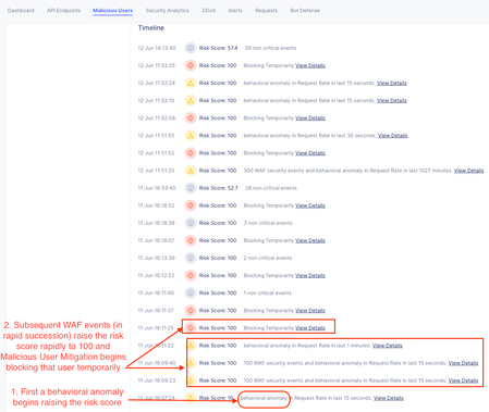
In a nutshell, the current state of the F5 Distributed Cloud WAF considers several factors before making a block/allow decision. The default configuration does the following: Operates in a monitoring mode, which logs WAF hits but doesn't block matches requests against high and medium attack signature accuracy classes Automatic Attack Signature tuning automatically suppresses likely false positives Bot Signature fill drop requests from clients that match known malicious bot signatures The focus here is that the default is to match based on signature accuracy, an approach that has been leveraged for years until the introduction of the AI-enhanced WAF. This deserves its own article, but to summarize here it pivots to a risk-based enforcement model instead of a pure signature match model. This decision is based on a custom model trained by F5 to identify requests that were riskier regardless of signature accuracy which improves both the block rate while lowering false positives further. But this isn't why you came here. Stepping outside of AI functions that have reduced false positives and better blocking, let's pivot to the challenge that many security teams face in actual businesses: you get stuck with a WAF forever in monitoring mode. Many on the security side of this equation might feel that watching malicious actors walk through the wide open front door has very little utility before the fact. There is a growing stash of events that could have been blocked or maybe get analyzed downstream to enforce a blocking mechanism (perhaps a SOC engineer maintaining a deny list?) in a purely reactive fashion. What if there was a better way? This is how we recently helped a customer find the best balance: Enter Malicious User Detection/Mitigation When Malicious User Detection is enabled, instead of looking at each request in isolation like a WAF or Firewall does, we look at the behavior of a particular client over time. This includes detecting anomalous behavioral changes, failed logins, unauthorized access, and most importantly for this article, all other Distributed Cloud security engine detections including but not limited to a WAF in monitoring mode. Why does this matter? An Application Firewall looks at the requests in their own context. We can assess risk inside the context of a given request, across all accuracy classes of signatures, but that context exists constrained to the request. Malicious User Detection adds the context of the user behavior over time. For instance, we will look at things that may never trigger a WAF block but because they are anomalous in time we can change the risk level of that user; with Malicious User Mitigation we can make a subtler decision to challenge a user with proportional responses. For instance, when a user transitions from no risk to low risk behavior, we can ensure they are running a browser with a javascript challenge. When they transition from low to medium risk we can present a captcha challenge. When they transition into high risk we can temporarily block that user. We can even identify users with a wide set of criteria than simple source IP. We can use XFF source IP, TLS fingerprints, headers, JWT claims, and other things, in a cascading list, to provide those mitigations in a very targeted way at an individual level. This means that one user that sends a request that triggers a WAF violation through a monitoring policy will be allowed through while another attacker that commits multiple WAF violations (or even just anomalous requests) will have mitigation applied in a progressive manner proportional to their risk. This is more subtle and targeted than a pure WAF block. An example Malicious User log from an Apache Bench test against an application with WAF monitoring mode and MUM: Configuration: App Firewall in Monitoring mode Enable Malicious User Detection and Mitigation in the HTTP Load Balancer 3. Save the HTTP Load Balancer Summary and Conclusions Pros: Mitigation are applied per-user instead of per signature A true false positive will be allowed through for a well-behaved user because where it might otherwise be blocked with a blocking WAF policy A malicious user can be stopped with mitigations based on anomalous behavior before they ever trigger a WAF block Cons: It takes a little more time to come to a decision to mitigate because behavior is a time-dependent variable Using behavioral analysis costs more than using WAF alone Key Point: Malicious User Detection/Mitigation with a monitoring WAF policy means you shift a block decision from a request context to a user-behavioral context which dramatically narrows the scope of impact from an application-related false positive. It is a safer middle ground to start doing something with all that WAF logging when you aren't allowed to turn on a blocking policy.369Views2likes1CommentFrom Chat to Config: Building an AI-Native MCP Server for F5 Distributed Cloud
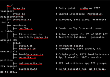
The Problem: F5 Distributed Cloud is Powerful but Verbose Anyone who has worked with F5 Distributed Cloud (XC) knows the platform is incredibly capable. HTTP load balancers, WAF policies, API security, origin pools, namespaces, service policies—the feature set is deep. But with depth comes complexity. A single POST to create an HTTP load balancer with WAF, HTTPS auto-cert, and an origin pool involves carefully crafting nested JSON across three or four separate API calls, each with its own spec structure. For experienced engineers, this is manageable. But what if you could just say: "Create an HTTPS load balancer for test-namespace, attach a WAF policy in blocking mode, origin server at 10.10.10.10 port 80 with an HTTP health check, auto-cert on port 443 with HTTP redirect" …and have all of that happen automatically, correctly, with dry-run safety by default? That's exactly what I built. This article walks through the F5 XC MCP Server—an open-source Model Context Protocol server that translates natural language commands from Claude Code or GitHub Copilot directly into F5 XC API calls. What is MCP? Model Context Protocol (MCP) is an open standard introduced by Anthropic that lets AI assistants (like Claude) call external tools and services through a structured interface. Think of it as a plugin system for AI — instead of the AI just generating text, it can actually do things: query APIs, read files, run commands, interact with platforms. An MCP server exposes a set of tools—typed functions with names, descriptions, and input schemas. When you ask Claude Code something like "list all my namespaces in F5 XC," it finds the right tool (xc_list_namespaces), calls it with the right parameters, and shows you the result. No copy-pasting API tokens into curl commands. No hunting through docs for the right endpoint path. MCP clients could be the popular AI coding tool, or any custom build MCP client, such as: Claude Code (via VS Code extension—the one I primarily used) GitHub Copilot (via VS Code extension) Any MCP-compatible client MCP servers can run locally (via stdio) or remotely (via HTTP/HTTPS). Architecture The server is built in TypeScript using the @modelcontextprotocol/sdk, with axios for F5 XC API calls and zod for input validation. The structure is intentionally simple: Key design decisions: Dry-run by default. F5_XC_DRY_RUN=true is the default. Every mutating call returns a preview of what would be sent rather than actually calling the API. This makes it safe to explore and prototype without fear. Set F5_XC_DRY_RUN=false when you're ready to go live. Dual auth. Supports both API token (Authorization: APIToken …) and mTLS certificate auth (https.Agent with PEM cert + key). The certificate extracted from the F5 XC .p12 credential file works directly. Dual transport. stdio for local use with Claude Code/Copilot; streamable HTTP/HTTPS for team-shared remote deployment. Terraform as fallback. When the REST API doesn't support an operation (more on this below), tools automatically generate ready-to-apply Terraform HCL using the volterraedge/volterra provider. The Four Use Cases The server covers four areas matching common F5 XC workflows: UC Tools Example operations UC-1 Identity Namespace CRUD, API credentials Create namespace, list users/groups, audit credentials UC-2 Load Balancer Origin pool CRUD, HTTP LB CRUD Create HTTPS LB with auto-cert, add origin pool UC-3 Security App Firewall (WAF) CRUD, Service Policy CRUD Create WAF in blocking mode, attach to LB UC-4 API Security API definition CRUD, App API group CRUD, raw request Import OpenAPI spec, create API group In total the server exposes 39 tools—enough to cover the majority of day-to-day F5 XC operations from a conversation. A Live Demo Walkthrough Here's a real session—every one of these was a natural language instruction to Claude Code, which called the appropriate MCP tool automatically. Step 1: Create a namespace "Create a new namespace called test-namespace" Step 2: Create an HTTP load balancer — then upgrade it "Create an HTTP load balancer named test-http-lb in test-namespace" The tool calls xc_create_http_lb with a minimal spec. State returns as VIRTUAL_HOST_READY in seconds. "Change protocol from HTTP to HTTPS port 443, use automatic certificate management from XC, add origin server 10.10.10.10 port 80 with default HTTP health check" This triggers three tool calls automatically: xc_raw_request → creates an HTTP healthcheck object xc_create_origin_pool → creates origin pool with 10.10.10.10:80, references the healthcheck Delete old LB + xc_create_http_lb → recreates as HTTPS with https_auto_cert, HTTP→HTTPS redirect, pool attached Note: F5 XC does not allow changing the LB type (HTTP → HTTPS) via PUT. The MCP server detected this and handled the delete-recreate flow automatically. The result: Step 3: Create and attach a WAF policy "Create a WAF policy named test-waf-policy" xc_create_app_firewall — blocking mode, default OWASP detection, default bot settings. Done in one call. test-waf-policy created ✓ Field Value Name test-waf-policy Namespace test-namespace Mode Blocking (blocks detected attacks) Detection Default OWASP ruleset Bot protection Default bot settings UID 8d350b72-5c8c-4e7c-b827-248b03067ed3 The WAF policy is ready. Would you like to attach it to test-http-lb? "Enable this WAF policy on test-http-lb" xc_update_http_lb — removes disable_waf, adds app_firewall reference. Verified with a GET to confirm disable_waf is gone and app_firewall.name is set. WAF policy enabled on test-httlp-lb ✓ Field Value WAF policy test-waf-policy (blocking mode) disable_waf removed LB state VIRTUAL_HOST_PENDING_A_RECORD Total time from zero to a WAF-protected HTTPS load balancer: under 2 minutes, all from natural language. The API Limitation Discovery — and the Terraform Fallback One of the most interesting findings during development: F5 XC's public REST API does not expose user/group write operations. Every path I tried returned either 404 or 501 Not Implemented: This is intentional by design—F5 XC routes user management through its Console UI. The Terraform volterraedge/volterra provider also didn’t help for users, group management. Rather than leaving the user with a dead end, I built a Terraform fallback: when a user group write fails, the tool’s response automatically includes: The AI can then call xc_tf_apply directly to execute it—or the user can copy the HCL and apply it themselves. The Terraform runner operates in isolated temp directories, cleans up after itself, and respects the global dryRun flag (plan instead of apply when dry-run is active). This pattern—REST first, Terraform as fallback—turned out to be a very useful architectural choice. It gracefully handles the gap between what the API exposes and what the platform can actually do. Deploying to Production: HTTPS with Automatic Certificates For a shared team tool, local stdio mode isn't enough. The server needs to be always-on, accessible over HTTPS, and with a real TLS certificate. The deployment stack on an Azure Ubuntu VM: Node.js 20 (via nvm) running the MCP server on port 3000 as a systemd service Caddy as a TLS-terminating reverse proxy—one config file, automatic Let's Encrypt The entire Caddy config: Caddy handles the ACME HTTP-01 challenge automatically. The Let's Encrypt certificate was issued in under 10 seconds after DNS propagated. Auto-renewal is built in—no cron jobs, no certbot timers. One gotcha worth noting: the default Caddy proxy timeout (30s) is shorter than some F5 XC API calls (namespace creation can take ~45s). The response_header_timeout 90s setting above is necessary. With this setup, the MCP endpoint is https://your-domain/mcp — usable from any MCP client without VPN or local server setup. Connecting Claude Code to the Remote Server Add this to your Claude Code MCP configuration (~/.claude.json or .claude/settings.json in your project): That's it. After a /mcp reload in Claude Code, all 39 tools are available. You can verify with: "Show me the F5 XC server status" Which calls xc_server_status and returns tenant, auth method, dry-run state, and Terraform auth status. Lessons Learned The F5 XC REST API is comprehensive for data plane operations, limited for identity management. Load balancers, WAF policies, origin pools, API definitions — all fully CRUD-able via REST. User and group management is not. Plan accordingly if your use case involves IAM automation. Dry-run mode is not optional — it's essential. Without it, a misunderstood instruction could delete a production load balancer. Making dry-run the default (and requiring explicit override per-call or globally) is the right design for any AI-driven ops tool. Tool descriptions matter more than you think. The quality of an MCP tool's description directly affects how accurately the AI uses it. Spending time writing precise, example-rich descriptions — including what fields are required, what values are valid, and what the return looks like — significantly improves the AI's ability to compose multi-step operations correctly. Graceful degradation beats hard failures. The Terraform fallback pattern is a good example. Rather than returning a cryptic API error and stopping, surfacing the equivalent HCL and offering to apply it keeps the workflow moving. Users get an answer even when the API says no. LB type changes require delete+recreate. The F5 XC API rejects PUT requests that change the load balancer type (e.g., HTTP → HTTPS). The MCP server handles this automatically by detecting the error and orchestrating the delete-recreate sequence — a good example of where the AI layer can absorb platform-specific quirks. What's Next This is v1.0 — functional, deployed, and covering the core use cases. Areas I'm exploring for future versions: API security scanning integration: trigger XC's web application scanning from the MCP server and return findings Multi-tenant support: switch tenants within a session without restarting the server Policy-as-code export: serialize existing LBs and WAF configs to Terraform HCL for IaC migration Audit/diff mode: compare current live config against a desired state and report drift Try It Yourself The server is open source on GitHub: https://github.com/gavinw2006/F5_XC_MCP_Server Prerequisites: Node.js 18+, an F5 XC tenant with an API token, and Claude Code or any MCP-compatible client. The first thing to try once connected: "Show me the F5 XC server status, then list all namespaces" Happy to hear feedback, questions, and PRs from the DevCentral community. If you build something on top of this—a new tool module, a different transport, integration with another F5 product—I’d love to know about it.615Views2likes2CommentsHow to use F5 Distributed Cloud to block (OFAC) Sanctioned Countries
Over the last several days, the climate has changed significantly in Eastern Europe, and I have been getting asked a lot about the possibility of blocking Office of Foreign Assets Control - Sanctioned Countries (OFAC) with F5 Distributed Cloud, and how to do it. The answer is quite simple; yes we can do it and its a pretty simple configuration. I think its also important to point out that this same process can be used to configure any other required GeoFencing policies as well. Do we also have ways to block DDOS and provide WAAP services? Also yes, but outside the scope of this article. In this article, I will focus on how to deploy & create: [Namespace] Service Policies Origin Pool(s) to send traffic to Distributed listener / load balancer with the security policy assigned View Security Events. Level Set Most of this article will be based around ClickOps deployment of this use-case. That said, the F5 Distributed Cloud is an API first platform, so everything can be done with your tools of choice for interaction with declarative APIs. I will include JSON manifests of the configured items as well to provide examples of what delcarations will resemble, as well as support direct import into the distributed cloud. It would be possible to say, set the policy configuration JSON into github as a source of truth, and have webhooks set up to push to the platform any time a change is made to ensure configurations stay within proper alignment. Who do we block? Before we can start blocking things, we need to know what exactly to block, so we need to acquire a list of OFAC Sanctioned Countries. There are a couple of options here as well. CSV straight from the source: https://home.treasury.gov/policy-issues/office-of-foreign-assets-control-sanctions-programs-and-information Dig through available data sources on Data.Gov: https://catalog.data.gov/dataset/consolidated-non-sdn-sanctions-list Third Party ACL Sites like Country Block List: https://www.countryipblocks.net/ofac.php (I cannot personally vouch for the accuracy of this content.) For the sake of brevity here, I will focus on just some top level country sanctions based on country code versus IP Subnet, but thats up to preference. Configuration Log in to your F5 Distributed Cloud Console. (If you do not have a tenant today, you should reach out to your F5 Account Team immediately and rectify the situation!) Service Policies for everyone! There are a couple of options for service policies in the platform. Shared Policies: Policies created in the Shared namespace, can be shared globally within your tenant. Benefit: Globally set policy baseline for all applications in your tenant. Namespace Policies: Policies created in a Namespace can only be shared within that namespace. Benefit: Namespace service policies applied by default to all listeners / load balancers. For this example, we will create the policy in a namespace. From the tiles, select Load Balancers, and then we need to ensure that we are in the proper namespace. (As with everyting on the platform, there are multiple ways to get places, and multple ways to configure things, so this will only cover 1 example of how.) Now we need to expand Security, hover over Service Policies, Click Service Policies, and in the new window click Add service policy. Populate the Name under metadata, leave attachment as Any Server, and set Select Policy Rules to Denied Sources. Now, we could use IP blocks, but for this example we will just use the Country List configuration parameter and enter country codes. This will pull from GeoIP validation. UPDATE: I have been getting a lot of notes on this article based on Ukraine versus Crimea, and how to specify since its not seperated out as a country code. Can we Allow Ukraine and block Crimea? Absolutely! For Crimea, we need to pull from another database, so for this example I am going to pull from https://bgpview.io/search/Crimea and we are going to block by ASN. So within our service policy, click Add item under BGP ASN Set. And on this screen we enter in all the ASN's that we discovered from the previous link. Then click Apply. (Making sure to now remove Ukraine from our Block List.) Then we need to determine Default Action. This is where you can cause some pain for yourself, so pay special attention when selecting Default action (“Default Action for requests from sources that do not belong to this list”), if you are using Next Policy, ensure the next policy allows traffic, or set the Default action to Allow, or the application will not receive any traffic. In this example I will only be using one policy, so I will set the Default Action to Allow (as noted in the JSON). Save and Exit. UPDATE 2: OK, you guys are killing me! Can we go to City Level or target regions outside of ASN? Yes! Here is how you do that. (I should plan better in the future for less edits!) Just to keep things clean, lets add a new Service Policy. This time, under Select Policy Rules, we are going to select Custom Rule List from the drop down. Then from here, we want to click Configure under Rules, then Add Item. Give our new rule a name, and click Configure under Rule Specification. From here, we are going to change the dropdown under Clients - Client Selection from Any Client to Group of Clients by Label Selector. Then under Selector Expression, Add Label. In the available selections you will find geoip.ves.io/city, country, and region (as well as some really cool IP Intelligence options but those are out of scope for this article.). Lets do a Region first to see how that works. Selct geoip.ves.io/region, then =, then start typing a region, for example Crimea. Once we have it set, scroll down and click Apply. Now, lets add another rule, but this time we are going to select city. We are already blocking Russia in our earlier policy, but just for an example lets add = Moscow. Now scroll down and click Apply. Thats it! Now we have policies to block based on GeoIP Country, Region, and City, as well as BGP ASN. We can apply all of them to our application at the same time. Now, lets say you just want to cheat, and copy and paste some JSON in, or you want to build it into a pipeline. You can go and check out the API specifications for Service Policy here: https://docs.cloud.f5.com/docs/api/service-policy The JSON would resemble the following for our first policy: { "metadata": { "name": "coleman-ofac-deny", "namespace": "m-coleman", "labels": {}, "annotations": {}, "description": "", "disable": false }, "spec": { "algo": "FIRST_MATCH", "any_server": {}, "rules": [ { "kind": "service_policy_rule", "uid": "c12f8c5d-44c2-495c-83e8-30842e9e0a7f", "tenant": "f5-sa-rnxeudss", "namespace": "m-coleman", "name": "ves-io-service-policy-coleman-ofac-deny-asn-list" }, { "kind": "service_policy_rule", "uid": "5d24d0d0-6c6b-4c7b-b5b3-4bec67c2ffed", "tenant": "f5-sa-rnxeudss", "namespace": "m-coleman", "name": "ves-io-service-policy-coleman-ofac-deny-country-list" }, { "kind": "service_policy_rule", "uid": "f9df0b83-21de-4c13-aebf-4e27fc580ed0", "tenant": "f5-sa-rnxeudss", "namespace": "m-coleman", "name": "ves-io-service-policy-coleman-ofac-deny-default-action" } ], "deny_list": { "ip_prefix_set": [], "asn_list": { "as_numbers": [ 204791, 205515, 208090, 28761, 41269, 43222, 43564, 49617, 59744, 8654 ] }, "asn_set": [], "country_list": [ "COUNTRY_BY", "COUNTRY_BA", "COUNTRY_BI", "COUNTRY_CF", "COUNTRY_CU", "COUNTRY_IR", "COUNTRY_IQ", "COUNTRY_KP", "COUNTRY_XK", "COUNTRY_LY", "COUNTRY_MK", "COUNTRY_SO", "COUNTRY_SD", "COUNTRY_SY", "COUNTRY_ZW", "COUNTRY_CD", "COUNTRY_LB", "COUNTRY_NI", "COUNTRY_RU", "COUNTRY_SS", "COUNTRY_VE", "COUNTRY_YE" ], "tls_fingerprint_classes": [], "tls_fingerprint_values": [], "default_action_allow": {} }, "simple_rules": [] } } And our second policy JSON puts us over the limit for the article, but all JSON from these configs are in the attached file. Origin Pools Origin Pools are where we send traffic to, so if you are familiar with BIG-IP its just the Pool, and if you are familiar with NGINX its our Upstream. All of the settings and nerd knobs that are part of origin pools are out of scope of this article, so we are just going to point our origin at a single public IP and move on. To create an Origin Pool, Expand the Manage Block, hover over Load Balancers, click Origin Pools, and then Add Origin Pool. Give the Origin Pool a Name under Metadata. Then under Origin Servers click Add Item so we can add an upstream server. For this example I am going to use a Public DNS Name of Origin Server, but you should use whichever applies best to your situation. Click Add Item once done, which will return us to the Origin Pool Config. Make sure to select the correct port, and any TLS settings for your environment. Click Save and Exit. Load Balancer / Listener Now that we have somewhere to send traffic, we need a way to receive traffic and assign security policies. We will be staying within scope for this use-case as well and not highlighting all of the details within the load balancer configuration. To create a Load Balancer, Expand the Manage Block, hover over Load Balancers, click HTTP Load Balancers, and then Add HTTP load balancer. Set a Name under Metadata. Under Basic Configuration, Domains, add a domain for the application. If you have delegated a DNS zone to the platform, we can automate DNS (and make certificate management super easy, but not required). Under Default Origin Servers, click Add Item, and in the Origin Pool drop down, select the pool that was created previously, then click Add Item. For VIP configuration we will leave as Advertise on Internet. You will notice under Security Configuration, Service Policies are already set to Apply Namespace Service Policies. Since I have a few policies in my namespace already, and I want to demonstrate OFAC policies, I am going to change this to Apply Specified Service Policies, and under Apply Specified Service Policies click Configure and select the previously created policy, then click Apply. From here click Save and Exit. Testing Using a VPN we can make sure that our policy is up and running. Since we did not configure a custom response page of any sort we should just get a 403 - Forbidden page. While users accessing from non OFAC countries will be able to access the application. Reporting We should be able to access the security events now as well, Expand Virtual Hosts, HTTP Load Balancers, and then over the load balancer we created earlier a hyperlink for Security Monitoring will show up, click it. We can see in the dashboard a L7 security event, and if we select Security Events, we will see that our VPN based request was flagged (l7_policy_sec_event, Rule to match CountryList). If its not totally legible, I VPN'd to Belarus and tried to access the page. Hint: Being able to use the JSON to copy policies is really great, I have used this in action with several customers to show how quickly we can backup and copy policies between environments in a few seconds. Thats it, now your web application is blocking traffic from OFAC sanctioned countries, and anyone else you want to keep out.7.7KViews9likes3Comments
Leverage BIG-IP 17.1 Distributed Cloud Services to Integrate F5 Distributed Cloud Bot Defense
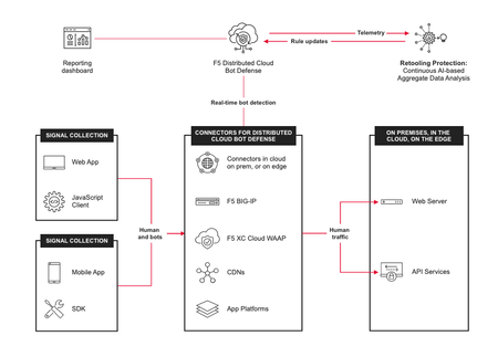
Introduction: The F5 Distributed Cloud (XC) Bot Defense protects web and mobile properties from automated attacks by identifying and mitigating malicious bots. The Bot Defense uses JavaScript and API calls to collect telemetry and mitigate malicious users. The F5 Distributed Cloud (XC) Bot Defense is available in Standard and Enterprise service levels. In both the service levels the Bot Defense is available for traffic form web, web scarping, and mobile. The web scrapping is only applicable to web endpoints. This article will show you how to configure and use F5 Distributed Cloud Bot Defense (XC Bot Defense) on BIG-IP version 17.1 and above and monitor the solution on F5 Distributed Cloud Console (XC Console). Prerequisites: A valid XC Console account. If you don't have an account, visit Create a Distributed Cloud Console Account. An Organization plan. If you don't have an Organization plan, upgrade your plan. Getting Started: Log In to F5 XC Console: If XC Bot Defense isn't enabled, a Bot Defense landing page appears. Select Request Service to enable XC Bot Defense. If XC Bot Defense is enabled, you will see the tiles. Select Bot Defense. Verify you are in the correct Namespace. If your Namespace does not have any Protected Applications you will see the following page. Click Add Protected Application When you select a Namespace that has been configured with Protected Applications you will see this page. Scroll down to Manage Click Applications Click Add Application The Protected Application page is presented. Enter: Name Labels Description Select the Application Region - US in this example Connector Type - BIG-IP iApp for this demo. Cloudfront and Custom are other available connectors Scroll to the bottom and Click Save and Exit That will take you back to the Protected Applications Page. Verify your Application is listed with all the Metadata you supplied. Click the three ellipses to the right. Scroll down into the highlighted area and click and Copy App ID, Tenant ID and API Key Copy and save each value to a location where you can access it in the next steps. That completes the configuartion of F5 XC Console. Log In to your BIG-IP You will Notice in version 17.1 and above you will have a new selection along the left pane called Distributed Cloud Services. Expand and you will see all the latest integrations F5 provides. Application Traffic Insight Bot Defense Client-Side Defense Account Protection & Authentication Intelligence Cloud Services This article as stated before will focus on Bot Defense. Look for future articles that will focus on the other integrations. On the Main tab, Click Distributed Cloud Services > Bot Defense > Bot Profiles and Select Create This will bring up the General Properties page where you will enter required and optional information. Mandatory items have a Blue line on the edge. Supply a Name Application ID - From previous step Tenant ID - From previous step API Hostname - Web is filled in for you API Key - from previous step In the JS Injection Configuration section, the BIG-IP Handles JS Injectionsfield is checked by default, if you uncheck the field then follow the Note given in the Web UI. Protected Endpoint(s) - Web - Supply either the URI or IP of the Host Application along with the path and method you are protecting on the protected endpoint. In the following image, I have selected Advanced to show more detail of what is available. Again Mandatory fields have a blue indicator. Here the Protection Pool and SSL Profile. Click Finished when complete. One final step to complete the setup. Go to the Main tab, Local Traffic > Virtual Servers > Virtual Serves List Select the Virtual Server you are going to apply the Bot Defense profile to. Click on Distributed Cloud Services on the top banner Under Service Settings > Bot Defense set to Enable and then select the Bot Defense Profile you created in the above steps. The click Update. You have now sucessfully integrated BIG-IP Distributed Cloud Service on version 17.1 with F5 Distributed Coud Bot Defense. One final visual is the dashboard for F5 Distributed Cloud Bot Defense. This is where you will observe and monitor what bots and actions have been taken against bots and your protected applications. F5 XC Bot Defense on BIG-IP 17.1 Demo: Conclusion: I hope you were able to benefit from this tutorial. I was able to show how quickly and easlity it is to configure F5 Dsitributed Cloud Bot Defense on BIG-IP v17.1 using the built in Distributed Cloud Services integration. Related Links: https://www.f5.com/cloud https://www.f5.com/cloud/products/bot-defense BIG-IP Bot Defense on 14.x-16.x5.7KViews3likes4CommentsDeploy Bot Defense on any Edge with F5 Distributed Cloud (SaaS Console, Automation)
XC Bot Defense Connector Strategy F5 Distributed Cloud Bot Defense meets you where you’re at when it comes to deployment flexibility. We make it ridiculously easy for you to deploy XC Bot Defense either in the cloud, on-prem, or as a hybrid configuration with pre-built connecters in leading application platforms and CDNs to make deployment easy and fast. Choose Your Path Within each deployment scenario, you can choose your path with the following options to deploy the specified Bot Defense environment using either the console deployment link or automation with terraform. Module 1 Deploy Bot Defense on Regional Edges with F5 Distributed Cloud Module 2 Deploy F5 XC Bot Defense for AWS Cloudfront with F5 Distributed Cloud Module 3 Deploy Bot Defense in Azure with BIG-IP Connector for F5 Distributed Cloud Module 4 Deploy Bot Defense in GCP Using BIG-IP Connector for F5 Distributed Cloud XC Bot Defense Scenarios The modules below lay out a framework for connecting and managing distributed app services for this scenario, with a focus on the three core use cases. MODULE 1: Deploy Bot Defense on Regional Edges with F5 Distributed Cloud In this scenario, we will be deploying our fictitious airline application into a Regional Edge location of our choosing via the VK8's service in XC. We'll walk through all of the required steps, provide the vk8's manifest file and front end this application with an XC HTTP Load Balancer. In addition, the HTTP Load Balancer will be used to front-end our application and enable our XC Bot Defense Service. Choose your path: Console Steps for XC Bot Defense on Regional Edges Automated Deployment of XC Bot Defense on Regional Edge via Terraform MODULE 2: Deploy F5 XC Bot Defense for AWS Cloudfront with F5 Distributed Cloud In this scenario, we will be deploying our fictitious application in AWS with the XC Bot Defense Connector for AWS Cloudfront Distributions. Choose your path: Console Steps to Deploy F5 XC Bot Defense for AWS Cloudfront Coming Soon*** Automated Deployment of XC Bot Defense for AWS Cloudfront MODULE 3: Deploy Bot Defense in Azure with BIG-IP Connector for F5 Distributed Cloud In this scenario, we will be deploying our fictitious application into Azure with the XC Bot Defense Connector for BIG-IP. Choose your path: Console Steps to Deploy F5 XC Bot Defense in Azure with BIG-IP Connector Automated Deployment of XC Bot Defense in Azure with BIG-IP Connector MODULE 4: Deploy Bot Defense in GCP Using BIG-IP Connector for F5 Distributed Cloud In this scenario, we will be deploying our fictitious application into GCP with the XC Bot Defense Connector for BIG-IP. Choose your path: Console Steps to Deploy F5 XC Bot Defense in GCP Using BIG-IP Connector Automated Deployment of XC Bot Defense in GCP with BIG-IP Connector For additional information, refer to these resources: Deploy Bot Defense on any Edge with F5 Distributed Cloud (SaaS Console, Automation) GitHub repository with the walk-through of the deployment steps & demo YouTube video series discussing the different aspects of this configuration DevCentral Learning Series: Edge Compute Get Started with F5 Distributed Cloud Services2.4KViews4likes2Comments